Fine particle handling unit, chip and sensor mounted with same, and methods for separating, capturing and sensing protein

a technology of a detection device and a processing unit, which is applied in the field of fine particle processing units, can solve the problems of extremely small treatment capacity of the particle treatment apparatus using the micro-channel, and the difficulty of adopting the device to fine particles of molecular level,

Inactive Publication Date: 2006-02-16
NEC CORP
View PDF7 Cites 90 Cited by
  • Summary
  • Abstract
  • Description
  • Claims
  • Application Information

AI Technical Summary

Benefits of technology

[0013] The particle manipulation unit of the present invention has the limitative permeation zone in the channel. This makes it possible to limit migration, towards the downstream side, of the particles beyond the branching point where the first channel and the second channel branch from each other. Of the particles in the liquid, which came through first channel to reach the permeation limiting zone, only those having predetermined geometries and sizes can permeate through the permeation limiting zone, and guided towards the downstream side of the first channel. It is also made possible to manipulate the direction of flow of specific particles out of those contained in the fluid, that is, those incapable of permeateting through the permeation limiting zone, and to guide only such particles towards the second channel. In this way, the particle manipulation unit of the present invention makes it possible to readily and efficiently control direction of flow of the particles in the liquid.
[0032] The particle manipulation unit of the present invention has, in the permeation limiting zone, the first drive means and the second drive means capable of making the particles move towards a plurality of directions which differ from each other. The channel is also provided with a plurality of obstacles. This makes it possible to stably separate the particles based on the surface property, geometry, size, deformation liability and so forth of the particles. The particles can exactly be separated, also because the width of entrance of the permeation limiting zone is configured as being narrower than the width of the permeation limiting zone.

Problems solved by technology

The particle treatment apparatus using the micro-channel has, however, been suffering from a problem of extremely small capacity of the treatment.
The conventional techniques have, however, been suffering from problems below.
It was, however, not easy to adopt the device to fine particles of molecular level, such as biological molecules, because the separation performance thereof depends on the geometry of the obstacles.
For example, separation of particles having a particle size of as small as 50 nm or less, such as proteins, demands a higher level of accuracy in the geometry of obstacles, but it is difficult for the current microfabrication technology to fabricate such level of fine geometry with a satisfactory accuracy.
Even for the case where particles having size of the order of millimeter, such as cells, are separated, there has also been requests on a high level of process accuracy for the obstacles in connection with size of particles to be separated, and realization of such process accuracy has demanded an expensive process technologies.

Method used


Image

  • Fine particle handling unit, chip and sensor mounted with same, and methods for separating, capturing and sensing protein
  • Fine particle handling unit, chip and sensor mounted with same, and methods for separating, capturing and sensing protein
  • Fine particle handling unit, chip and sensor mounted with same, and methods for separating, capturing and sensing protein

Examples


first embodiment

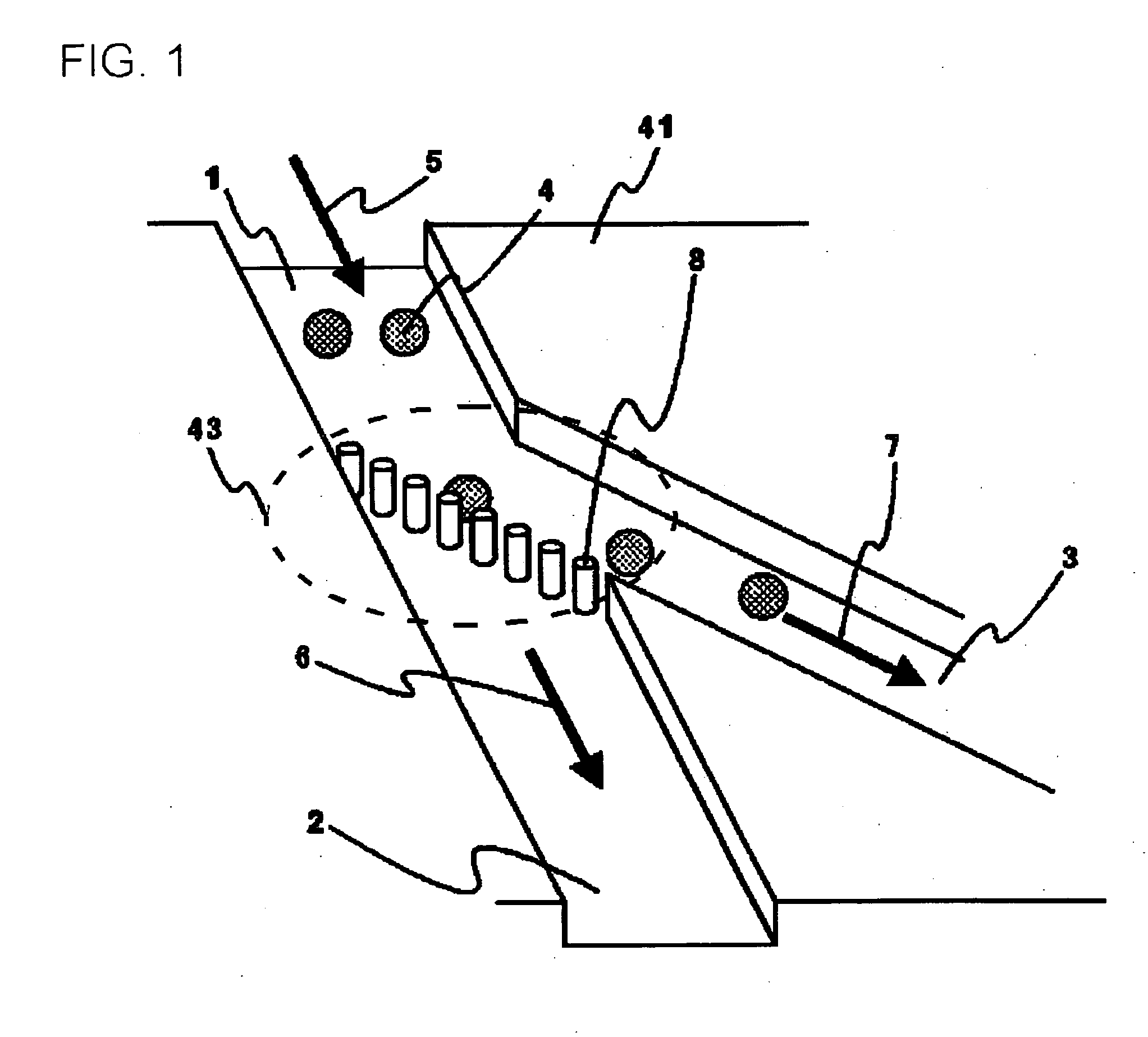
[0072] This embodiment relates to a particle manipulation unit manipulating flow of particles contained in a sample liquid, and guiding them to predetermined directions, with the aid of obstacles formed in a channel. FIG. 1 is a perspective view showing an exemplary configuration of a particle manipulation unit of this embodiment. As shown in FIG. 1, the configuration is such that a channel 1 formed on a substrate 41 is branched into a channel 2 and a channel 3 at a branching point 43, and that an obstacle portion, in which a plurality of columnar obstacles 8 are arranged as being spaced by regular gaps, is disposed at the branching point of the channel 1, channel 2 and channel 3.

[0073] First, a suspension containing the particles 4 is filled on the upstream side of the channel 1. Size of the particles 4 may typically be of the order of millimeter or smaller. It may still further be of the order of micrometer or smaller. The suspension respectively flows in the direction indicated ...

second embodiment

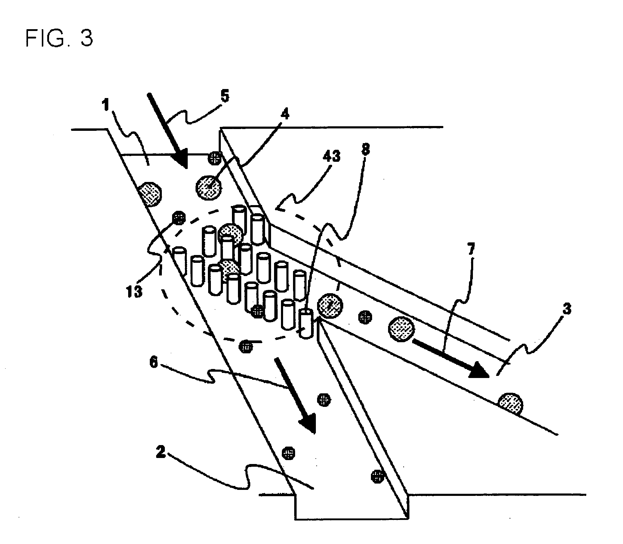
[0099] This embodiment relates to a particle manipulation unit manipulating flow of particles contained in a sample liquid, and guiding them to predetermined directions, with the aid of obstacles formed in a channel. This embodiment differs from the first embodiment in having a region in which multiple stages of obstacle portions are formed. FIG. 3 is a perspective view showing an exemplary configuration of a particle manipulation unit of this embodiment.

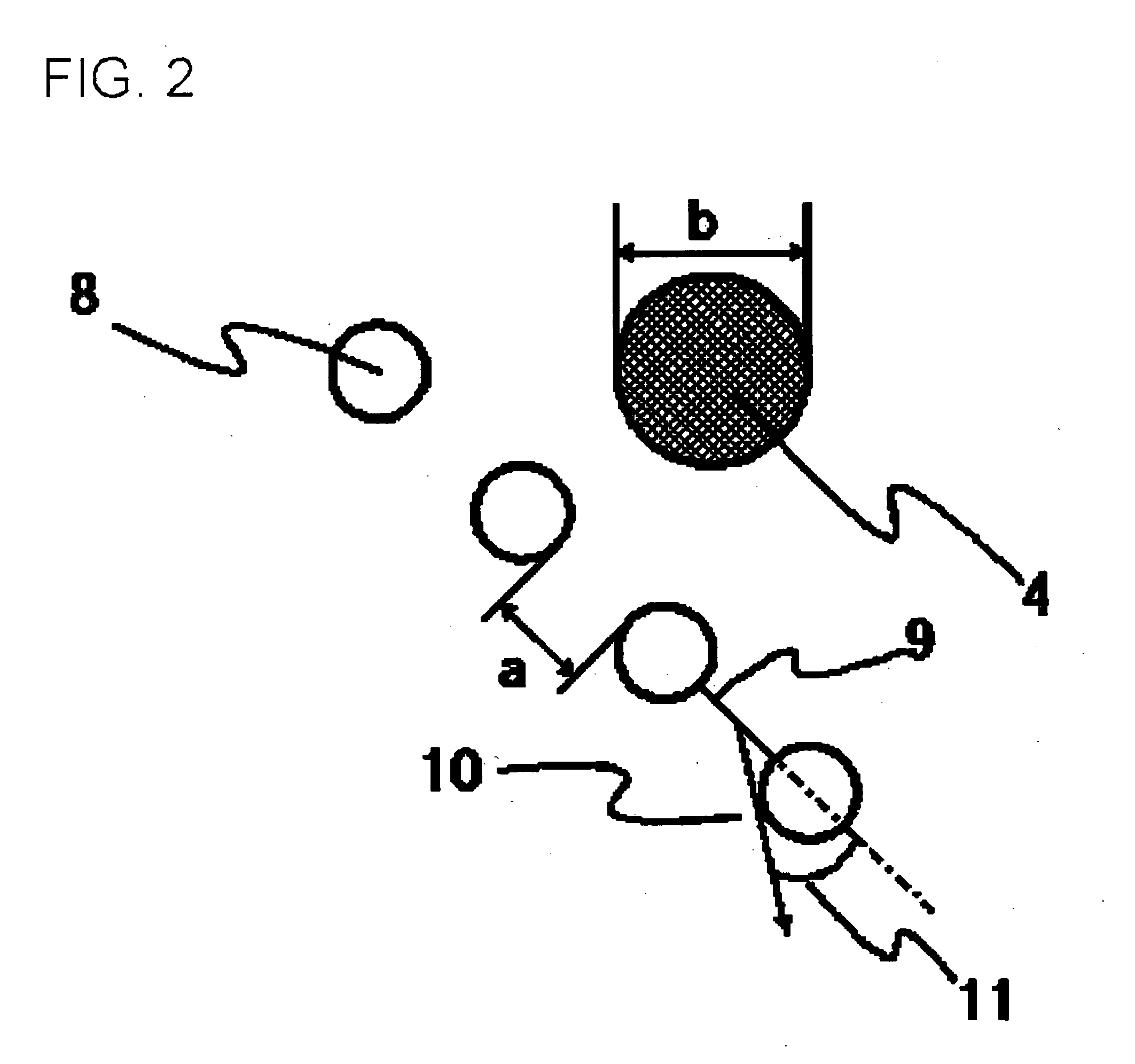
[0100]FIG. 4 is a top view showing the obstacles 8 disposed at the branching point 43, and particles present in the upstream side of the branching point 43. Next paragraphs will describe a mechanism of manipulating direction of flow of the particles 4 by the obstacle. As shown in FIG. 4, the structure of arrangement of multiple stage of obstacles 8 has a unit cell 12 indicated by a dashed line formed therein. As for width of gaps in the unit cell 12, as shown in FIG. 4, width “a” of the gap is set smaller, and width “c” of the gap ...

third embodiment

[0106] This embodiment relates to a unit manipulating the particle flow, having an array structure of the obstacles configured by unit cells, each of which having a trench structure formed on the wall surface of the channel, capable of interacting with particles of a predetermined size. FIG. 5 is a perspective view showing an exemplary particle manipulation unit of this embodiment. As shown in FIG. 5, a channel 14 is formed on a substrate 47. The sample liquid, having particles 15 suspended therein, is filled on the upstream side of the channel 14. The particles 15 flow in the direction indicated by an arrow 16 in FIG. 5. Similarly to the first embodiment, force making the particles 15 flow in the direction of arrow 16 may be generated by a method such as electrophoresis, dielectrophoresis or the like, or by any other forces exerted on the particles 15.

[0107] As shown FIG. 5, the channel 14 has an array structure, in which a trench structure 17 configures a unit cell, formed on the...


PUM

PropertyMeasurementUnit
particle sizeaaaaaaaaaa
angleaaaaaaaaaa
angleaaaaaaaaaa

Abstract

A channel (1) formed in a substrate (41) branches into channels (2, 3) at a branch point (43). On this branch point, obstacles (8) having a columnar structure are aligned at certain intervals.

Description

FIELD OF THE INVENTION [0001] The present invention relates to a particle manipulation unit, a chip and a detection device having the same mounted thereon, and methods of separating, capturing and detecting proteins. RELATED ART [0002] With advancement in recent micro-electro-mechanical system (MEMS) technologies, trials have been made on particle treatment making use of micro-channels in particular in the field of biological MEMS. For example, there has been proposed a fractionation apparatus having obstacles for electrophoretic use fabricated therein by microfabrication technologies, in place of using a polymer gel (Patent Document 1). This raised industrial advantages in that it would be no more necessary to prepare polymer gels and would improve the reproducibility. The particle treatment apparatus using the micro-channel has, however, been suffering from a problem of extremely small capacity of the treatment. [0003] As a solution for this problem, there has been proposed a meth...

Claims


Application Information

Patent Timeline
Patent Type & Authority Applications(United States)
IPC IPC(8): G01N33/558G01N27/62B01D29/00B01D57/00B01D57/02B01D61/18B01D67/00B01D69/00B01D71/02B01L3/00B81C1/00G01N1/10G01N27/64G01N33/53G01N35/08G01N37/00
CPCB01D29/00B01D61/18B01D67/0062B01D69/00B01D71/02B01D71/027G01N33/5302B01L3/502753B01L3/502761B01L2200/0647B01L2200/0652B01L2300/0816B01L2400/086B01L3/502746
Inventor HATTORI, WATARUBABA, MASAKAZUSANO, TORUIIDA, KAZUHIROKAWAURA, HISAOSOMEYA, HIROKO
Owner NEC CORP
Why Eureka
Try Eureka