Internal combustion engine with auto ignition

a technology of internal combustion engine and auto ignition, which is applied in the direction of machines/engines, electrical control, mechanical equipment, etc., can solve the problems of delayed ignition time of pre-injection and/or main injection, and achieve the effect of reducing the amount of pre-injection fuel and minimizing the wetness of the wall

Inactive Publication Date: 2006-02-23
DAIMLER AG
View PDF11 Cites 50 Cited by
  • Summary
  • Abstract
  • Description
  • Claims
  • Application Information

AI Technical Summary

Benefits of technology

[0019] In a further refinement of the invention, the pressure of the fuel introduced into the combustion chamber is changed during an injection process. This is intended to avoid wetting of the walls of the combustion chamber with fuel. The injection pressure is preferably varied as a function of the operating point and/or in accordance with a counter pressure prevailing in the combustion chamber, so that the wetting of the wall with fuel is minimized.
[0020] According to a further refinement of the invention the pre-injection

Problems solved by technology

Furthermore, the ignition time of the pre-injection and/or main injection may be de

Method used


Image

  • Internal combustion engine with auto ignition
  • Internal combustion engine with auto ignition
  • Internal combustion engine with auto ignition

Examples


first embodiment

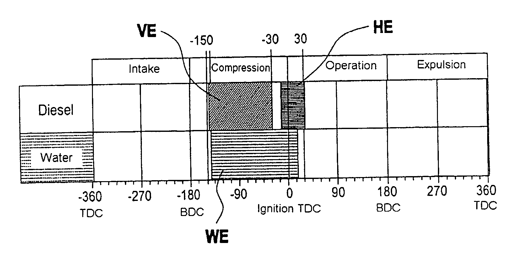
[0044]FIG. 7 shows such a fuel / water injection strategy for the internal combustion engine 1 for achieving a combustion chamber pressure profile according to FIG. 12. Here, in the compression stroke, first part of the fuel is injected into the combustion chamber 8 as a pre-injection, and this pre-injection can be performed in the intake stroke and / or compression stroke. The injection of water WE is started just before the start of the pre-injection VE with the latter being ended before the end of a main injection HE. The pre-injection which is performed brings about good distribution of the fuel in the combustion chamber so that a homogenous fuel / air mixture which is mixed with the injected water is formed. Using the injection of water delays the ignition of the pre-injected quantity of fuel and reduces the rise in pressure so that the center point of the combustion is displaced in the retarded direction. If the quantity of water were not used, the center point of the combustion acc...

second embodiment

[0046] In the fuel injection strategy according to FIG. 8, the injection of the quantity of water WE does not start until after the pre-injection VE has ended so that the quantity of water is not introduced until after the ignition of the homogenous mixture.

third embodiment

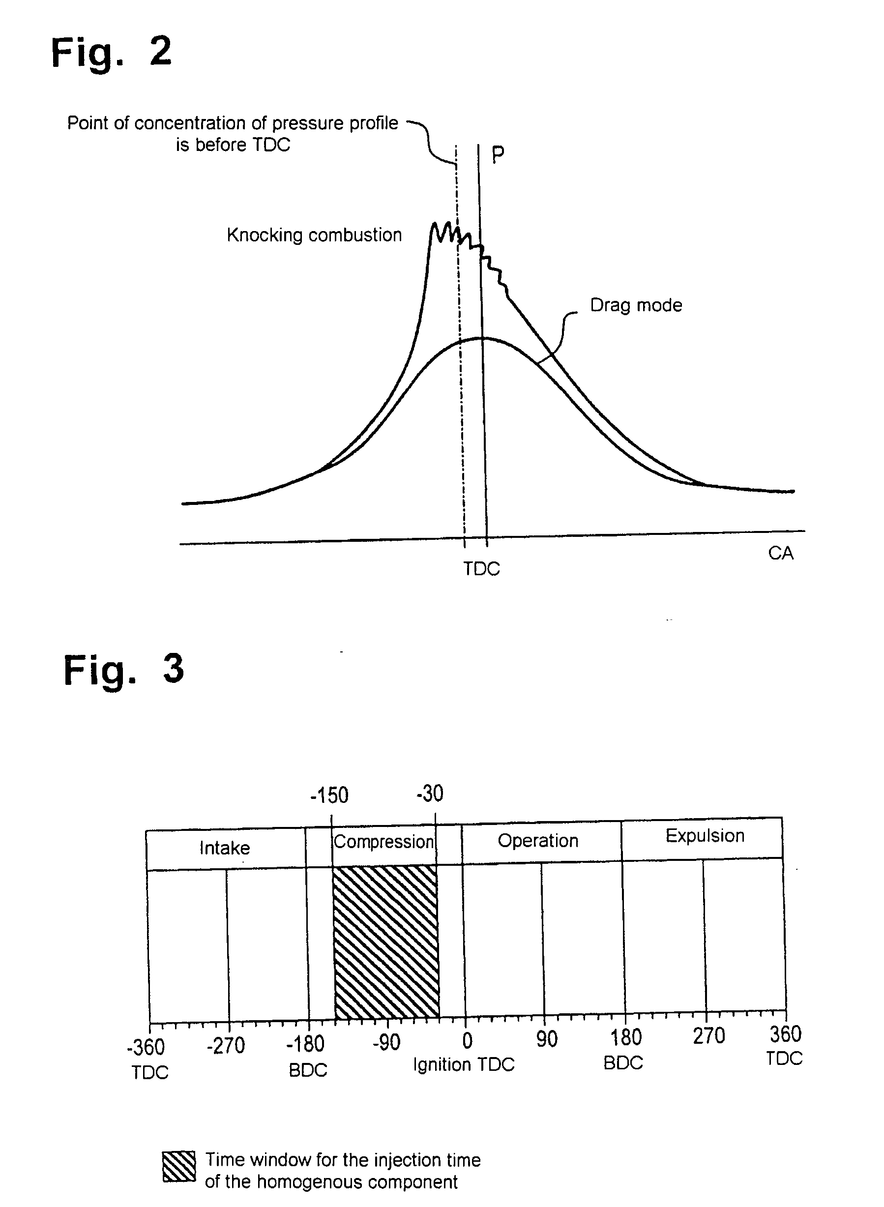
[0047] the quantity of water WE is added to the fuel during the pre-injection VE and during the main injection HE within the injection device 13 in such a way that the water is injected into the combustion chamber 8 together with the fuel as a fuel / water emulsion in accordance with the injection strategy illustrated in FIG. 9. The objective of this injection strategy is that the aimed-at cooling effect is ensured so that the start of ignition is shifted and the rise in pressure is reduced during the pre-injection VE and the temperature level of the pre-injection and that of the main injection are lowered. In this context, the pre-injection VE of the fuel / water emulsion takes place between 150° CA and 30° CA before the TDC. The main injection HE of the fuel / water emulsion is performed between 20° CA before the TDC and 30° CA after the TDC.


PUM


Abstract

In a method for operating an internal combustion engine in which fuel is injected directly into a combustion chamber in a pre-injection and a main fuel injection step, and, if appropriate, also in a post-injection step by means of an injection nozzle with a plurality of injection bores, the injection of fuel takes place in a timed fashion and, to limit pressure and temperature during combustion of the fuel in the combustion chamber, a quantity of water is introduced into the combustion chamber during or after the pre-injection step.

Description

[0001] This is a Continuation-In-Part application of International application PCT / EP2004 / 003339 filed Mar. 30, 2004 and claiming the priority of German application 103 15 199.4 filed Mar. 4, 2003.BACKGROUND OF THE INVENTION [0002] The invention relates to a method for operating an internal combustion engine with auto-ignition, in particular a diesel internal combustion engine, in which fuel is injected into a combustion chamber in different stages. [0003] In direct injection internal combustion engines with auto-ignition, due to the principle involved the heterogeneous kind of combustion control by the auto-ignition of the injected fuel inevitably leads to very high pressures and high combustion temperatures in the combustion chamber, which, in particular, cause high NOx emissions. Furthermore, as a result of the fuel-rich zones considerable quantities of particles of soot are formed which are partially oxidized at the high temperatures present. In order to avoid the disadvantages ...

Claims


Application Information

Patent Timeline
IPC IPC(8): F02B47/02F02B3/00F02B3/06F02B3/10F02B15/00F02D41/40F02M25/03F02M43/00F02M43/04F02M45/04
CPCF02B3/06F02B47/02F02D41/402F02M25/0227F02M43/04F02M45/04Y02T10/44F02M25/03F02D41/3035Y02T10/40
Inventor RAAB, ALOISSCHNABEL, MARTIN
Owner DAIMLER AG
Why Eureka
Try Eureka