Heat-dissipating device with heat pipe

Inactive Publication Date: 2006-02-23
INVENTEC CORP
View PDF9 Cites 20 Cited by
  • Summary
  • Abstract
  • Description
  • Claims
  • Application Information

AI Technical Summary

Benefits of technology

[0017] Therefore, the heat-dissipating device with heat pipe according to the present invention can achieve heat transmission through the heat pipe without bending the heat pipe, t

Problems solved by technology

Although the advanced semiconductor fabrication and IC (integrated circuit) design technologies have successfully reduced the size and improved the integration of electronic elements as well as provided multi-functional integration in the recent decade, there are still some new problems caused thereby, which are difficult to solve and would degrade reliability of the electronic elements.
A reason may be the impossibility for the electronic elements, which require electric power to drive operation thereof, to reach 100% working efficiency, such that the wasted power is converted to heat energy and greatly increases an operating temperature of the entire system.
If the operating temperature exceeds a tolerable range, errors would occur in the operation of such system; even worse, the system may fail or burn out due to overheat at the excessively high temperature.
For the aforemention

Method used


Image

  • Heat-dissipating device with heat pipe
  • Heat-dissipating device with heat pipe
  • Heat-dissipating device with heat pipe

Examples


Embodiment Construction

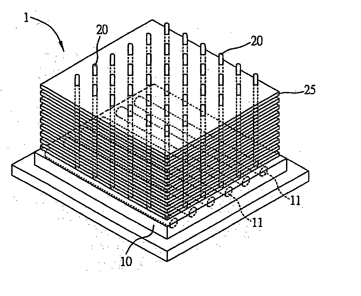
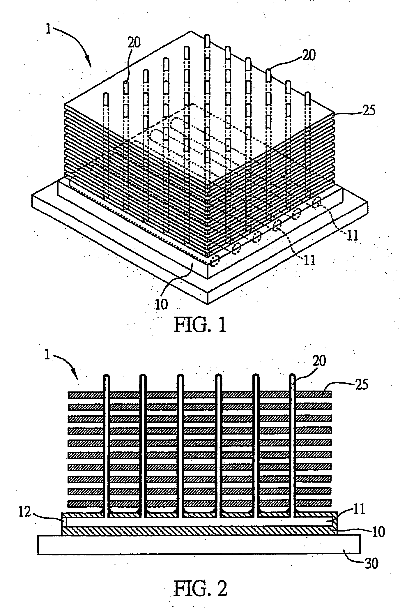
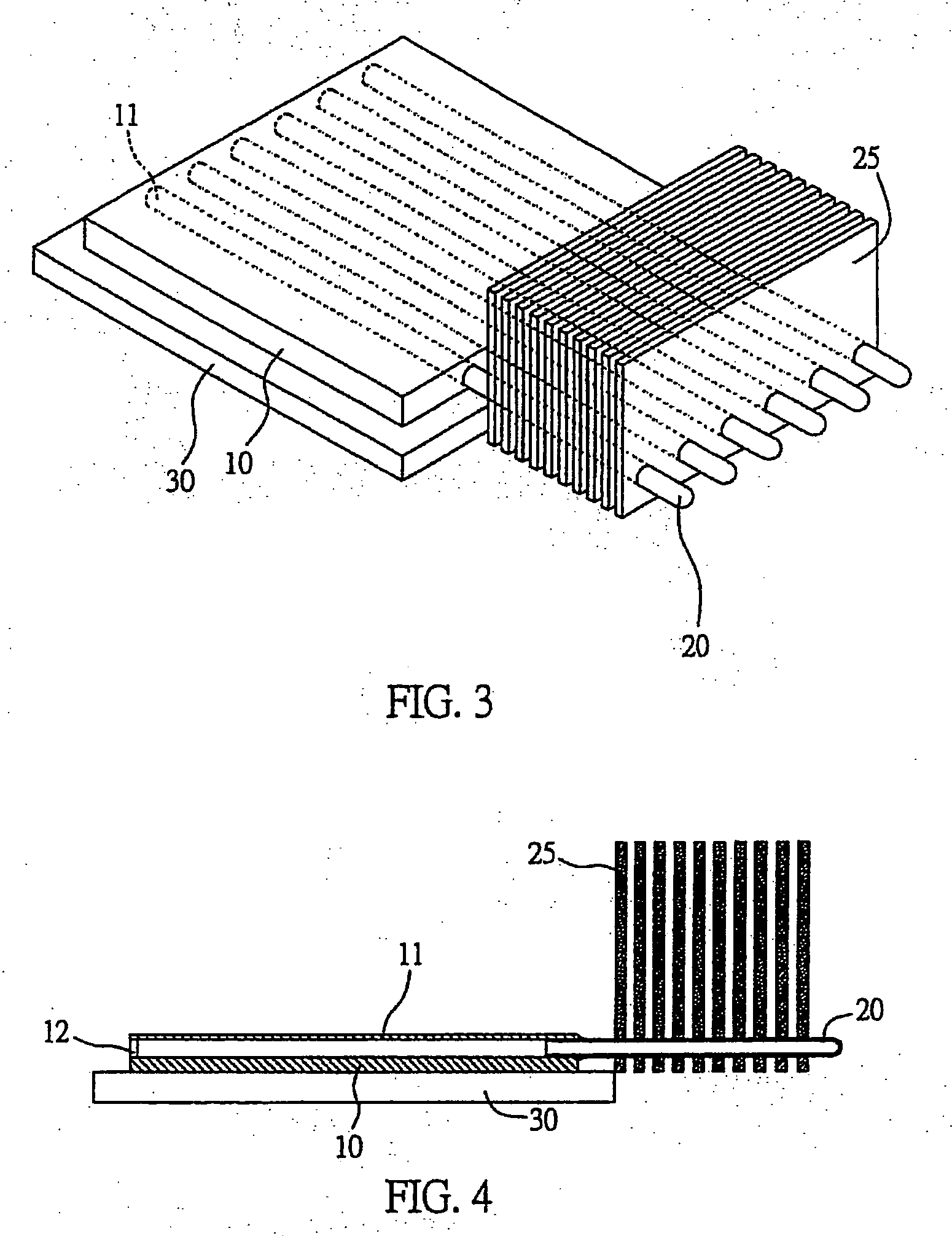
[0026]FIGS. 1 and 2 are schematic diagrams of a heat-dissipating device with heat pipe 1 according to a first preferred embodiment of the present invention, which comprises a base 10; a plurality of parallel pipe spaces 11 formed in the base 10 and penetrating at least one side of the base 10; a plurality of parallel heat pipes 20 vertically mounted on the base 10 and connected to the pipe spaces 11 respectively, such that each of the heat pipes 20 communicates with one of the pipe spaces 11, and the heat pipes 20 arranged in the same row communicate with the same single pipe space 11; and a plurality of heat-dissipating fins 25 attached to the heat pipes 20, wherein the heat-dissipating fins 25 are shaped as plates and are arranged on the heat pipes 20 in parallel and spaced from each other by a constant distance. Moreover, a working fluid (not shown) is filled in the pipe spaces 11 of the base 10, such that the working fluid when being evaporated by heat can enter inner spaces of ...


PUM


Abstract

A heat-dissipating device with heat pipe includes a base having a plurality of pipe spaces therein; a plurality of heat pipes vertically mounted on the base and connected to the pipe spaces respectively; a working fluid filled in the pipe spaces; and a plurality of heat-dissipating fins attached to the plurality of heat pipes and spaced from each other by a predetermined distance. This heat-dissipating device can achieve heat dissipation without bending the heat pipes.

Description

RELATED APPLICATION DATA [0001] The present application claims priority from prior Tiawanese application number 092313390 filed Aug. 23, 2004, incorporated by reference herein in its entirety. FIELD OF THE INVENTION [0002] The present invention relates to heat-dissipating devices, and more particularly, to a heat-dissipating device with heat pipe, which is applicable to an electronic device. BACKGROUND OF THE INVENTION [0003] Along with the globalization era, human's requirements of efficiency and convenience for working pace have become far more expected than the past. How to achieve multi-functionality of living needs within the most efficient timing becomes an important consideration for a consumer to purchase various living products in the market. For electronic products, a research and development trend thereof has aimed to produce new generation of products that are compact in size, have multiple functions and are highly efficient so as to satisfy the requirements of consumers...

Claims


Application Information

Patent Timeline
IPC IPC(8): H05K7/20G06F1/20H01L23/427
CPCH01L23/427H01L2924/0002H01L2924/00
Inventor LI, CHIN-YUANLIN, MAO-CHING
Owner INVENTEC CORP
Why Eureka
Try Eureka