Antenna control unit and phased-array antenna
- Summary
- Abstract
- Description
- Claims
- Application Information
AI Technical Summary
Benefits of technology
Problems solved by technology
Method used
Image
Examples
embodiment 1
[0062] Hereinafter, a first embodiment of the present invention will be described with reference to FIG. 1.
[0063] In the first embodiment, a phase shifter that is employed for a phased-array antenna of the present invention will be described.
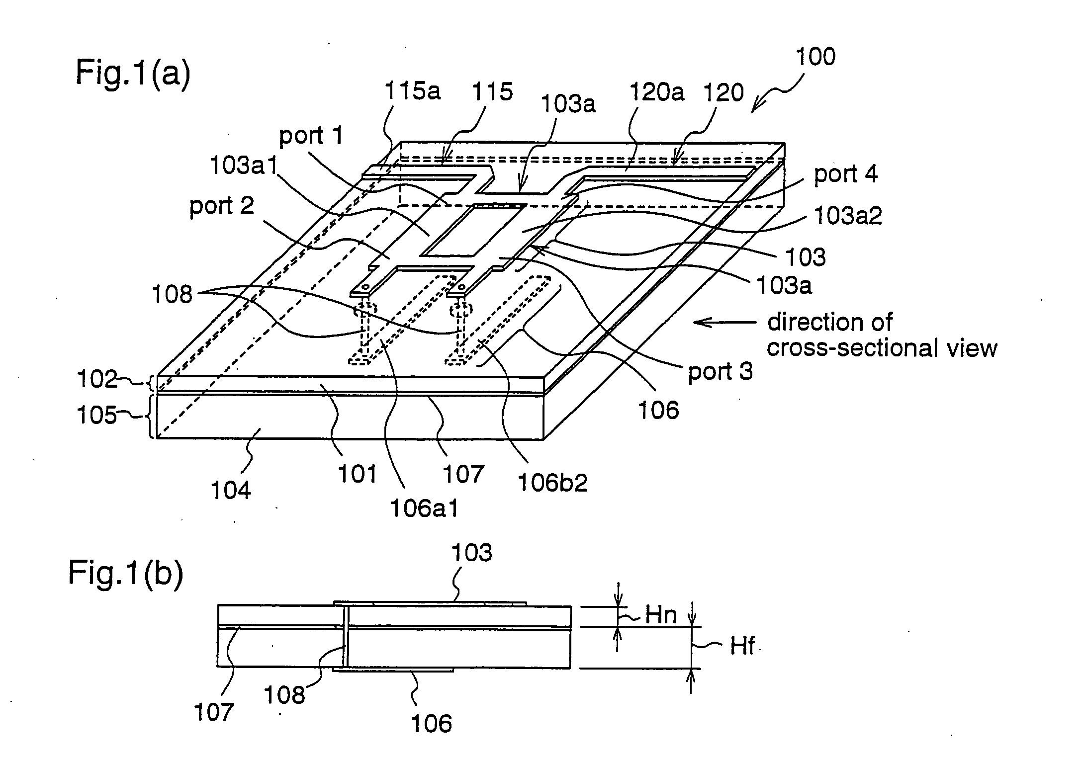
[0064] FIGS. 1 are a perspective view (FIG. 1(a)) and a cross-sectional view (FIG. 1(b)) illustrating a construction of the phase shifter according to the first embodiment, which is employed for the phased-array antenna of the present invention.
[0065] In FIGS. 1, reference numeral 100 denotes a phase shifter. Numeral 101 denotes a paraelectric base material, numeral 102 denotes a paraelectric transmission line layer, numeral 103 denotes a microstrip hybrid coupler, numeral 104 denotes a ferroelectric base material, numeral 105 denotes a ferroelectric transmission line layer, numeral 106 denotes a microstrip stub, numeral 107 denotes a ground conductor, and numeral 108 denotes a through hole by which the microstrip hybrid coupler 103 and the m...
embodiment 2
[0080] A second embodiment of the present invention will be described with reference to FIGS. 2.
[0081] In this second embodiment, a phase shifter that is employed for a phased-array antenna of the present invention will be described.
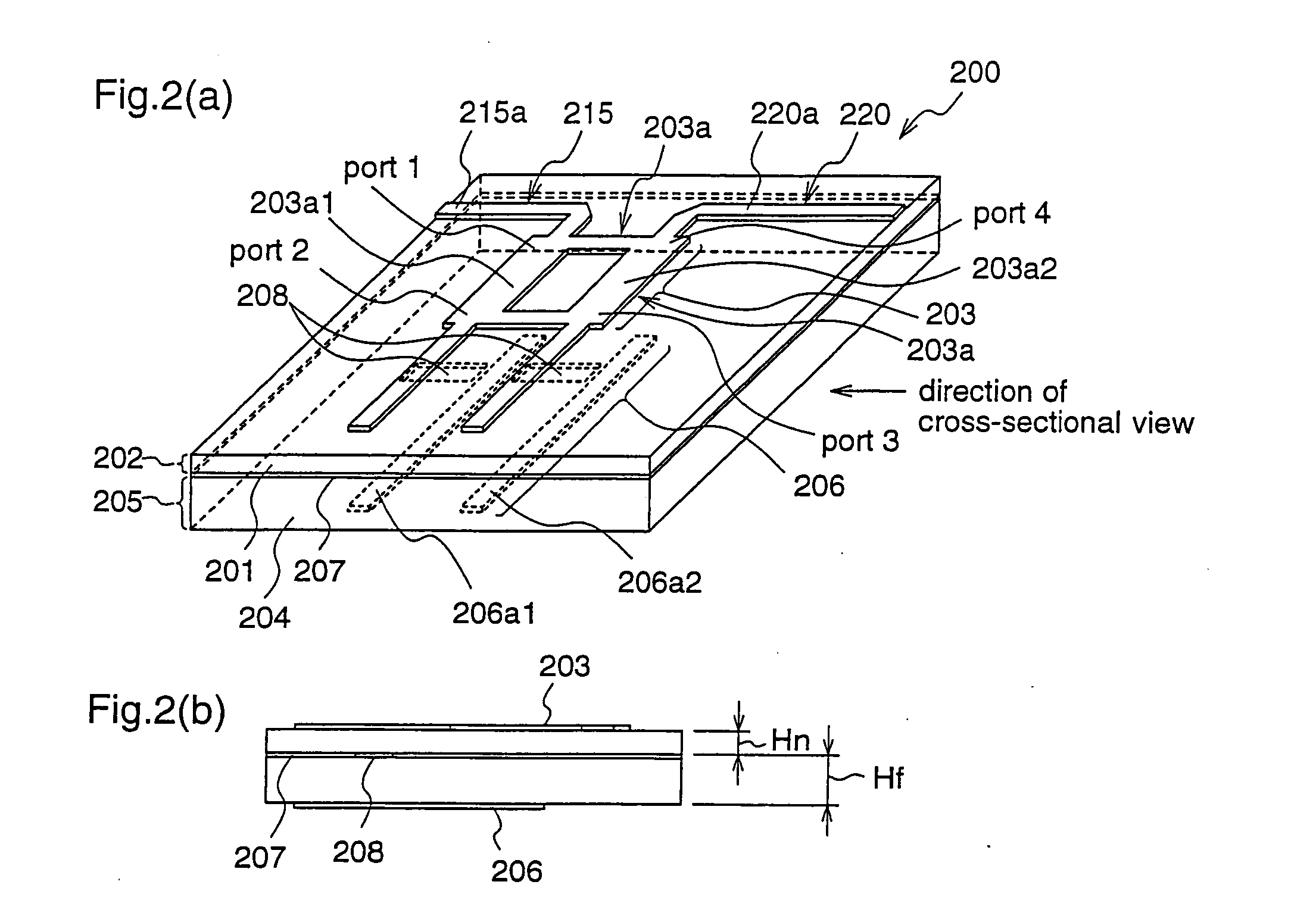
[0082] FIGS. 2 are a perspective view (FIG. 2(a)) and a cross-sectional view (FIG. 2(b)) illustrating a construction of the phase shifter according to the second embodiment, which is employed for the phased-array antenna of the present invention.
[0083] In FIGS. 2, reference numeral 200 denotes a phase shifter. Numeral 201 denotes a paraelectric base material, numeral 202 denotes a paraelectric transmission line layer, numeral 203 denotes a microstrip hybrid coupler, numeral 204 denotes a ferroelectric base material, numeral 205 denotes a ferroelectric transmission line layer, numeral 206 denotes a microstrip stub, numeral 207 denotes a ground conductor, and numeral 208 denotes a coupling window that is formed in the ground conductor 207, for electroma...
embodiment 3
[0098] A third embodiment of the present invention will be described with reference to FIGS. 3.
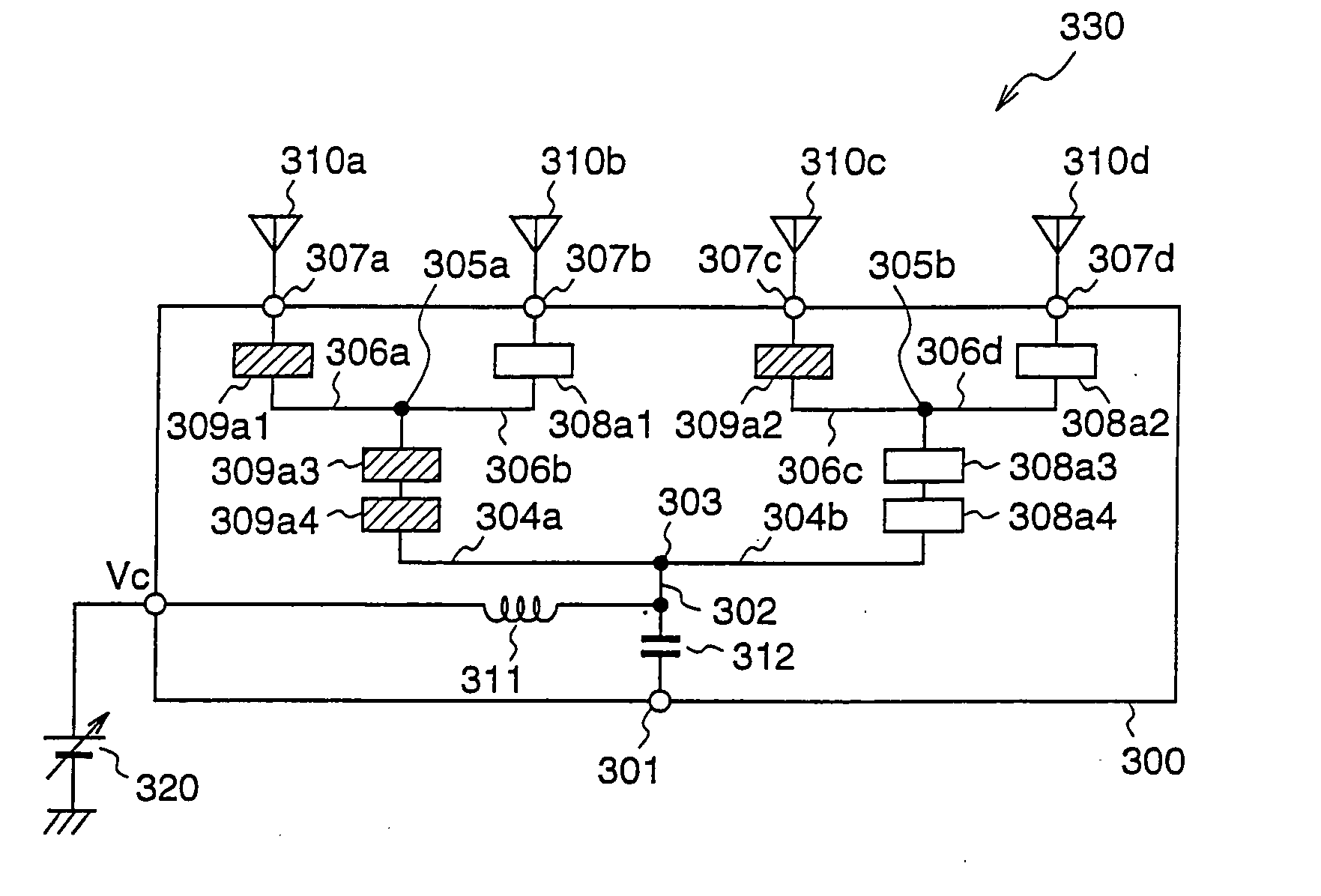
[0099]FIG. 3(a) is a diagram illustrating a construction of a phased-array antenna according to the third embodiment, and FIG. 3(b) is a diagram showing directivities of the phased-array antenna according to the third embodiment in a case where a beam tilt voltage is applied and a case where a beam tilt voltage is not applied.
[0100] In FIG. 3(a), a phased-array antenna 330 according to the third embodiment comprises an antenna control unit 300, a beam tilt voltage 320 for performing control of the directivity (beam tilt) as shown in FIG. 3(b), and four antenna elements 310a-310d. The antenna control unit 300 comprises an input terminal (feeding terminal) 301, four antenna terminals 307a-307d, four phase shifters 308a1-304a4, four loss elements 309a1-309a4, high frequency blocking element 311, a DC blocking element 312, a transmission line (feeding line) 302 from the input terminal 301, t...
PUM
 Abstract
Description
Claims
Application Information
 - R&D
- Intellectual Property
- Life Sciences
- Materials
- Tech Scout
- Unparalleled Data Quality
- Higher Quality Content
- 60% Fewer Hallucinations
Browse by: Latest US Patents, China's latest patents, Technical Efficacy Thesaurus, Application Domain, Technology Topic, Popular Technical Reports.
© 2025 PatSnap. All rights reserved.Legal|Privacy policy|Modern Slavery Act Transparency Statement|Sitemap|About US| Contact US: help@patsnap.com


