Continuous in-line manufacturing process for high speed coating deposition via a kinetic spray process

a manufacturing process and high-speed technology, applied in the direction of superimposed coating process, manufacturing tools, liquid/solution decomposition chemical coating, etc., can solve the problems of unable to successfully spray particle sizes and material compositions, the success of the spray process to date, and the difficulty of accelerating large particles to high velocities

Inactive Publication Date: 2006-02-23
F W GARTNER THERMAL SPRAYING
View PDF85 Cites 32 Cited by
  • Summary
  • Abstract
  • Description
  • Claims
  • Application Information

AI Technical Summary

Benefits of technology

[0007] In another embodiment, the present invention is a kinetic spray nozzle system comprising: a gas / powder exchange chamber connected to a first end of a powder / gas conditioning chamber having a length along a longitudinal axis of equal to or greater than 20 millimeters; a converging diverging supersonic nozzle, the supersonic nozzle having converging section separated from a diverging section by a throat, the diverging section comprising a first portion and a second portion, the first portion having a cross-sectional area that increases along a length of the first portion and the second portion having a substantially constant cross-sectional area along a length of the second portion; and the converging section connected to a second end of the powder / gas conditioning chamber opposite the first end.

Problems solved by technology

Typically, the powder gas, which is used to drive the powder to the exchanger chamber, is not heated to prevent powder from clogging the powder pipeline.
Harder particles generally need a higher velocity to result in adherence and it is more difficult to accelerate large particles to high velocities.
The prior art system has been shown to work with many different types of particles, however, some particle sizes and material compositions have not been successfully sprayed to date.
These attempts have been largely unsuccessful.
In addition, the coating density and deposition efficiency of the particles can be very low with harder to spray particles.
There is a limit, however, to the main gas velocities and temperatures that can be achieved within the system.
If the main gas temperature is too high the powder particles begin to adhere to the inside of the nozzle, which causes poor deposition and requires a nozzle cleaning.
Although the co-pending system improved the deposition efficiency for difficult to spray powders by increasing the particle temperatures it, however, has limitations for some very hard powders, powders that are hard with low melting temperatures, or with very large particles.
Certain particle populations such as brazing alloys formed from, for example, aluminum, silicon, and zinc, still are difficult to deposit because they become gummy in the nozzle and stick to its interior when the particle temperatures are too high, which reduces deposition efficiency.
Such traverse speeds are far too slow to make them useful when a manufacturing environment requires high deposition efficiency with high traverse speeds in the range of 25 to 250 centimeters per second.

Method used


Image

  • Continuous in-line manufacturing process for high speed coating deposition via a kinetic spray process
  • Continuous in-line manufacturing process for high speed coating deposition via a kinetic spray process
  • Continuous in-line manufacturing process for high speed coating deposition via a kinetic spray process

Examples


Embodiment Construction

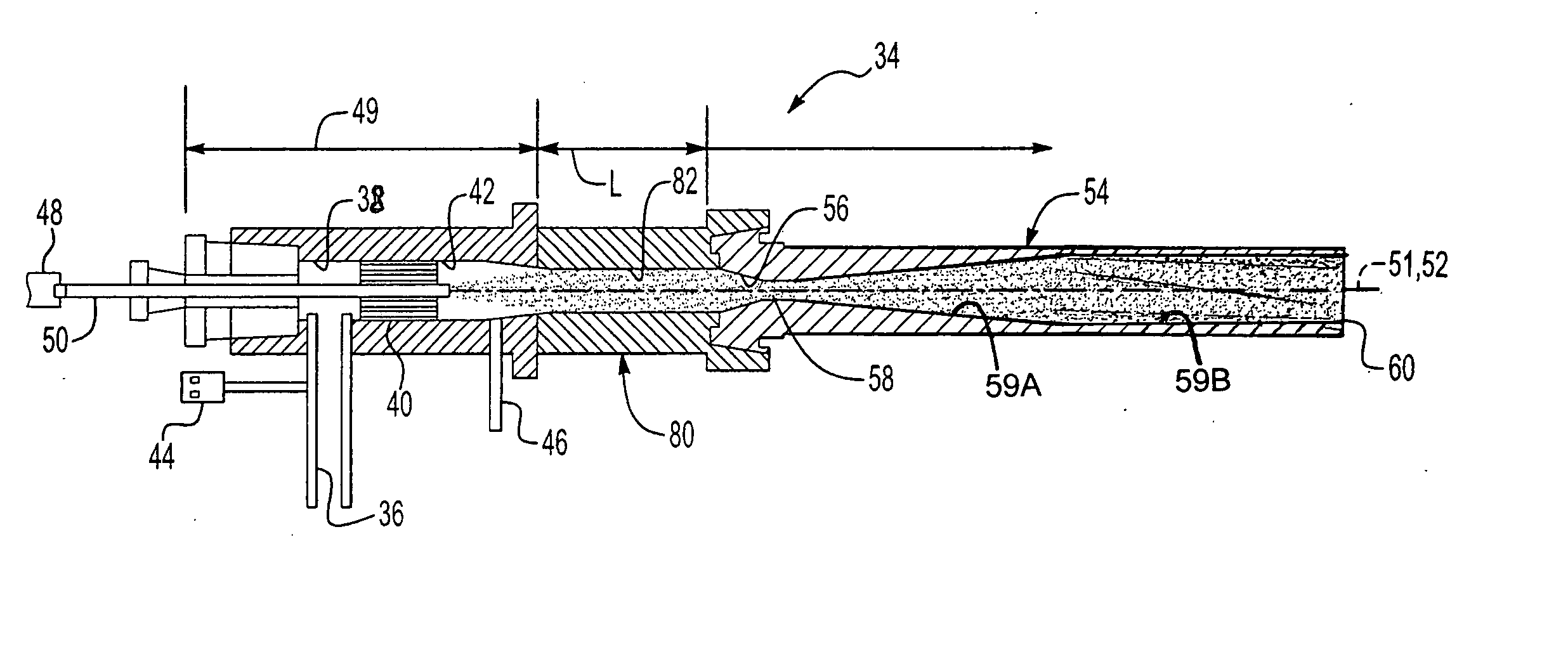
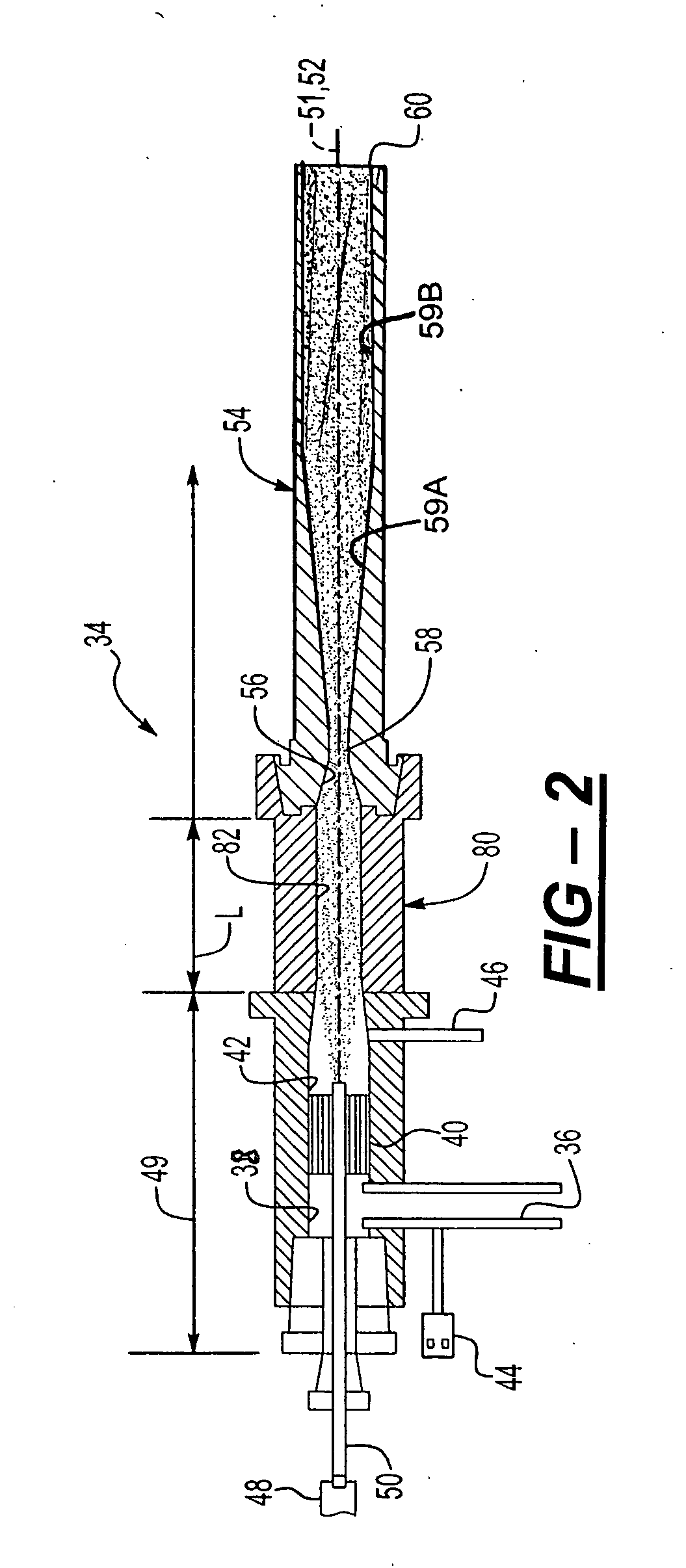
[0019] The present invention comprises a dramatic improvement to the kinetic spray process and nozzle system as generally described in U.S. Pat. Nos. 6,139,913 and 6,283,386.

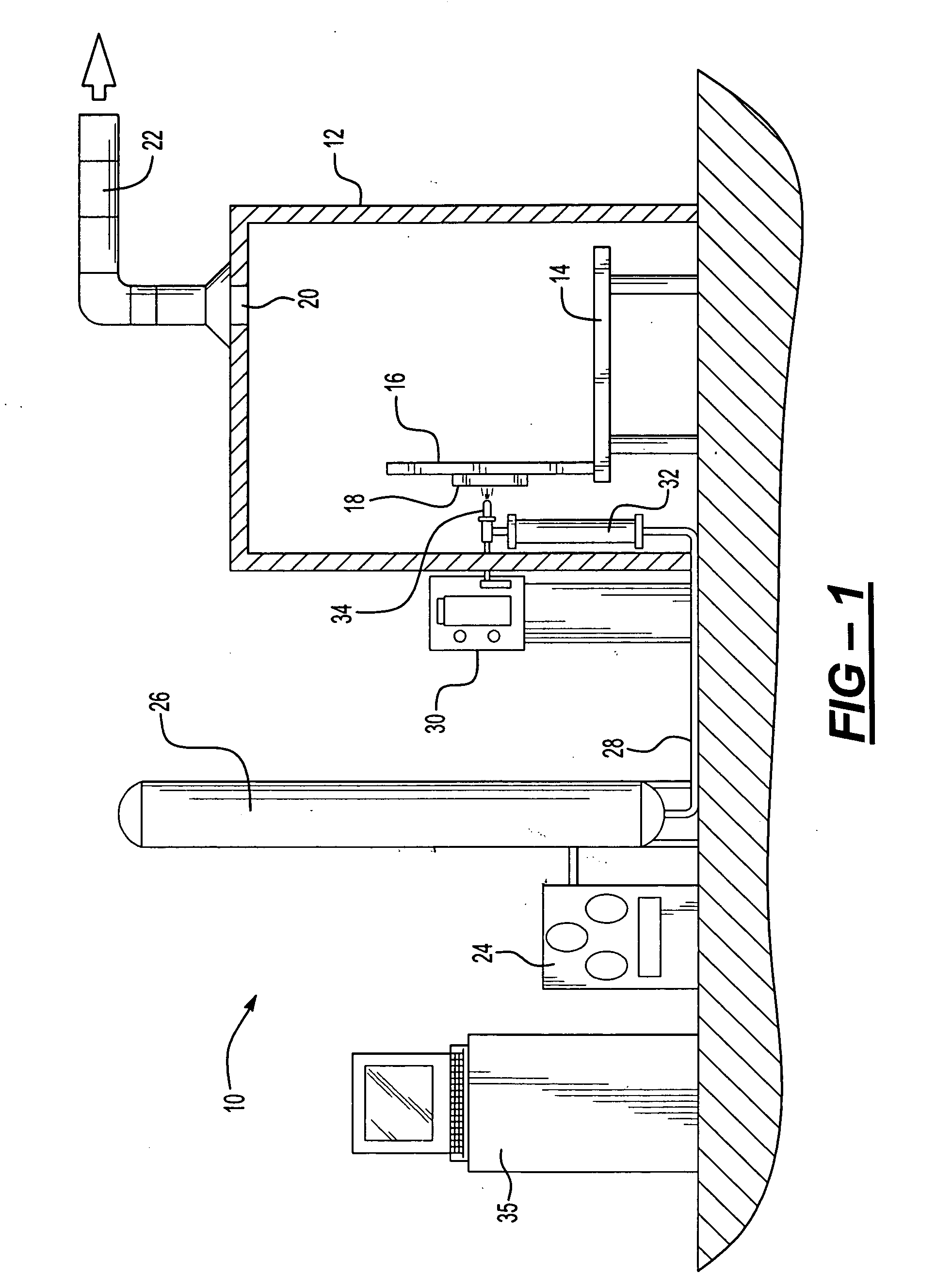
[0020] Referring first to FIG. 1, a kinetic spray system for use of a nozzle designed according to the present invention is generally shown at 10. System 10 can include an enclosure 12 in which a support table 14 or other support means is located. A mounting panel 16 fixed to the table 14 supports a work holder 18. Work holder 18 can have a variety of configurations depending on the type of substrate to be coated. For example, work holder 18 can be configured for the present invention as a plurality of high speed rollers capable of moving a substrate past a nozzle 34 at traverse speeds in excess of 250 centimeters per second. In other embodiments, work holder 18 can be capable of movement in three dimensions and able to support a suitable workpiece formed of a substrate material to be coated. The enclosure 12 c...


PUM

PropertyMeasurementUnit
lengthaaaaaaaaaa
lengthaaaaaaaaaa
lengthaaaaaaaaaa

Abstract

An improved kinetic spray system and a method for using the same in a high speed manufacturing environment are disclosed. The improved kinetic spray nozzle system comprises: a gas / powder exchange chamber connected to a first end of a powder / gas conditioning chamber having a length along a longitudinal axis of equal to or greater than 20 millimeters; a converging diverging supersonic nozzle, the supersonic nozzle having a converging section separated from a diverging section by a throat, the diverging section comprising a first portion and a second portion, with the first portion having a cross-sectional area that increases along a length of the first portion and with the second portion having a substantially constant cross-sectional area along a length of the second portion; and the converging section connected to a second end of the powder / gas conditioning chamber opposite the first end. The method includes: use of the disclosed nozzle system with the addition of hard particles that permit maximum enhancement of particle temperature while not permitting clogging of the nozzle; use of controlled particle feed rates to match the desired very high traverse speeds; and use of pre-heating of the substrate to clean it an to enhance particle bonding. With the disclosed nozzle system coupled with the disclosed methods one can apply kinetic spray coatings at traverse speeds of over 200 centimeters per second with a deposition efficiency of over 80 percent.

Description

TECHNICAL FIELD [0001] The present invention relates to coating a substrate by a kinetic spray process, and more particularly, to an improved nozzle system to permit high speed continuous in-line coating deposition using a kinetic spray system. INCORPORATION BY REFERENCE [0002] U.S. Pat. No. 6,139,913, “Kinetic Spray Coating Method and Apparatus”, and U.S. Pat. No. 6,283,386 “Kinetic Spray Coating Apparatus” are incorporated by reference herein. BACKGROUND OF THE INVENTION [0003] The prior art for kinetic spray systems generally discloses a kinetic spray system having a nozzle system that includes a gas / powder exchange chamber directly connected to a converging diverging deLaval type supersonic nozzle. The system introduces a stream of powder particles under positive pressure into the exchange chamber. Typically, the powder gas, which is used to drive the powder to the exchanger chamber, is not heated to prevent powder from clogging the powder pipeline. A heated main gas is also int...

Claims


Application Information

Patent Timeline
Patent Type & Authority Applications(United States)
IPC IPC(8): B05D1/08B05D1/12B05C5/00
CPCB05B7/00C23C24/04B05D1/02B05D3/12
Inventor HAN, TAEYOUNGZHAO, ZHIBOGILLISPIE, BRYAN A.SMITH, JOHN R.ROSEN, JOHN S. JR.
Owner F W GARTNER THERMAL SPRAYING
Why Eureka
Try Eureka