
Method for cleaning industrial equipment with pre-treatment

Active Publication Date: 2006-03-02
ECOLAB USA INC
View PDF20 Cites 64 Cited by
  • Summary
  • Abstract
  • Description
  • Claims
  • Application Information

AI Technical Summary

Benefits of technology

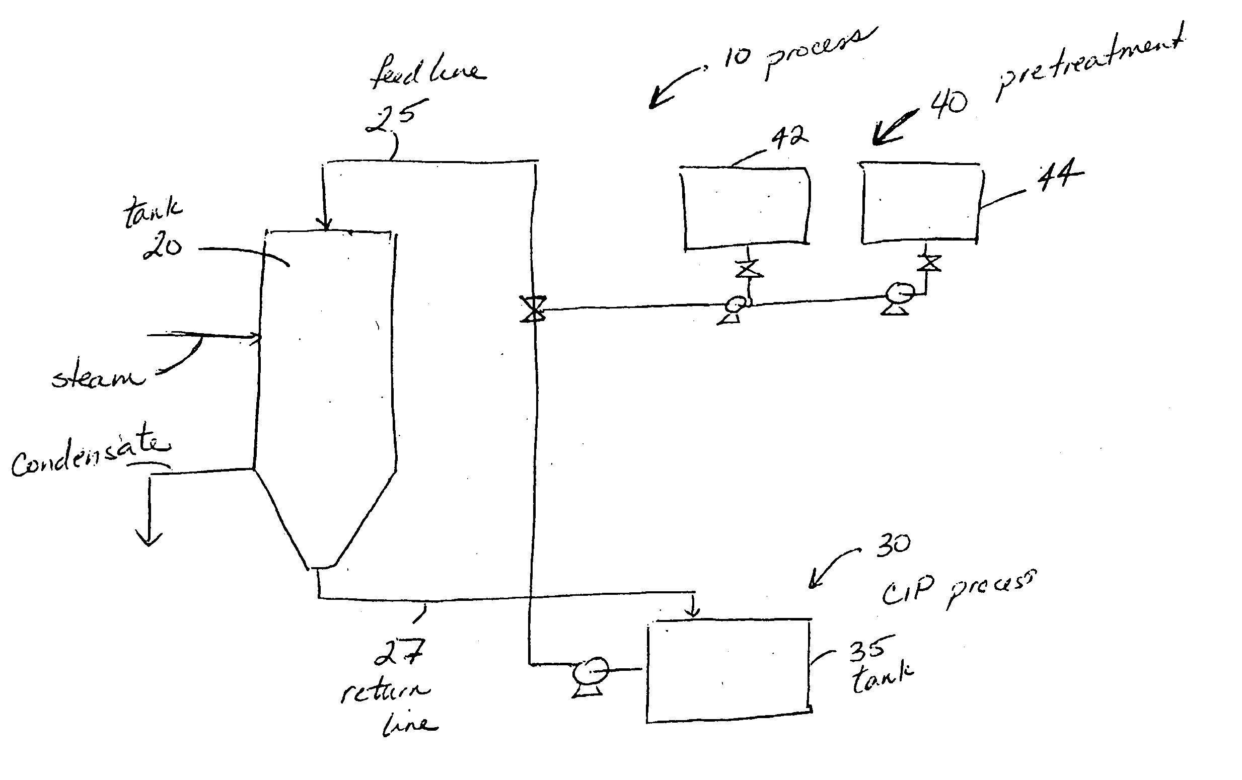
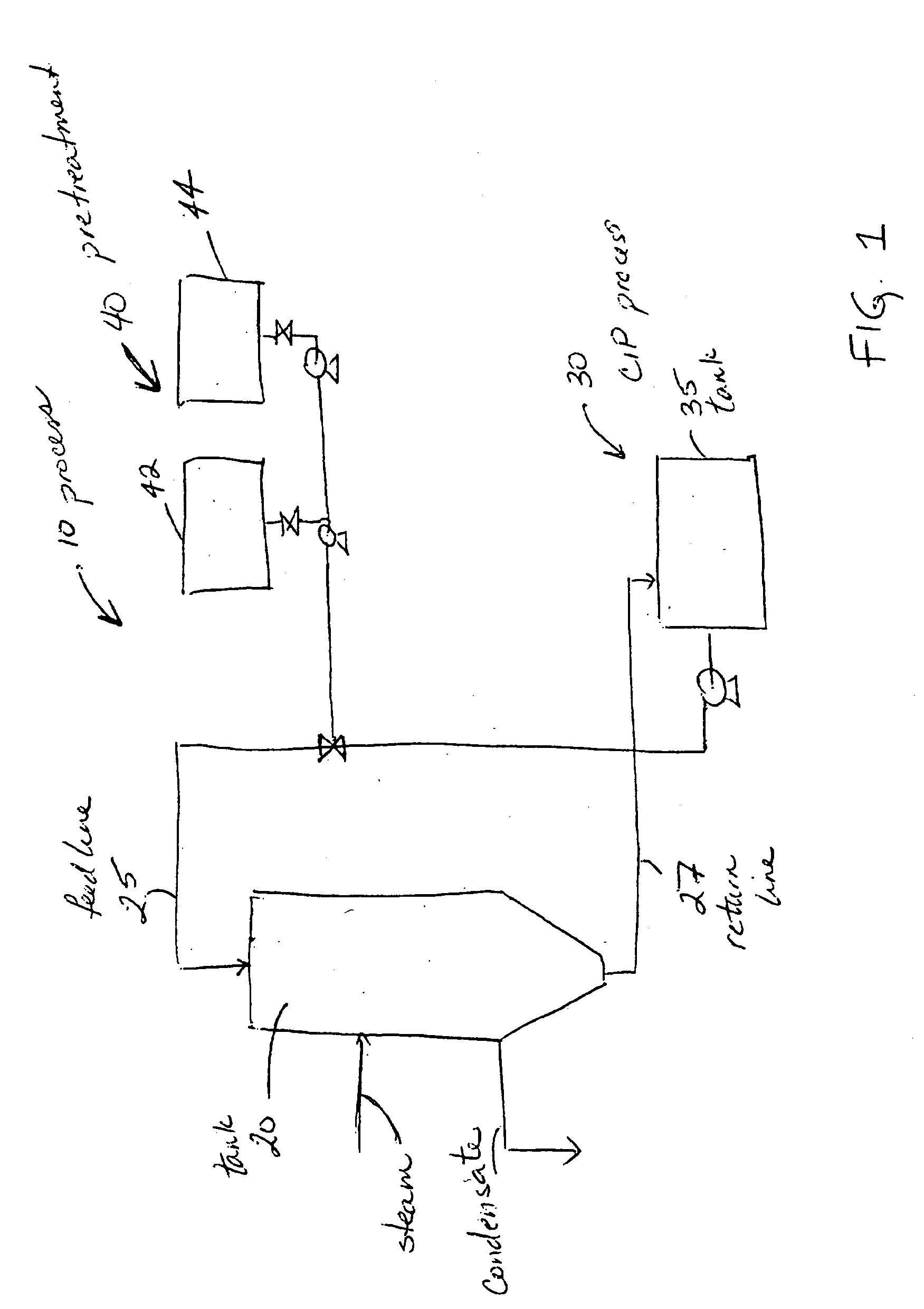
[0014] In another aspect, the invention is directed to a method that includes pre-treating the soiled surfaces with a strong alkaline solution. A conventional clean-in-place process follows this pre-treatment step. It has been found that a conventional clean-in-place process using an acidic detergent after the strong alkaline pre-treatment step provides particularly effective results.
[0015] Either of the pre-treatments, either acidic or alkaline, may include a penetrant. The addition of a penetrant improves the degree of softening of the soil, and thus facilitates the removal of the soil. The concentration of penetrant in a pre-treatment solution is at least 0.01 and usually at least 0.15%. A concentration of about 1% is acceptable.

Problems solved by technology

In many industrial applications, such as the manufacture of foods and beverages, hard surfaces commonly become contaminated with soils such as carbohydrate, proteinaceous, and hardness soils, food oil soils and other soils.
The removal of such carbohydrate soils can be a significant problem.
Food and beverage soils are particularly tenacious when they are heated during processing.
All of the evaporation plant equipment should be cleaned, however, the actual evaporator typically has the most difficult soiling problems.
When that surface is a heat exchange surface, the soil becomes thermally degraded rendering it even more difficult to remove.
The layer of soil acts as an insulator between the heat and the product being heated, thereby reducing the efficiency of the heat exchange surface and requiring more energy to create the same effect if the heat exchange surface were clean.
When the heat exchange surface is an evaporator, the difference between a clean heat exchange surface and a soiled heat exchange surface can mean the difference in millions of dollars in energy costs for an evaporator plant.
Clean-in-place processing requires a complete or partial shutdown of the equipment being cleaned, which results in lost production time.
Many times, the equipment is not thoroughly cleaned, due to the large downtime needed.

Method used


Image

  • Method for cleaning industrial equipment with pre-treatment
  • Method for cleaning industrial equipment with pre-treatment
  • Method for cleaning industrial equipment with pre-treatment

Examples


example 1

[0074] Test Procedure

[0075] Solid milk pellets were prepared by mixing 3 grams of dry milk power and 3 grams of soil. The resulting mix was pressed in a die for 30 seconds at 10,000 lb, and then more pressure was added to again apply 10,000 lb for 30 additional seconds. The pellets were placed in screens and immersed in the pre-treatment solutions, described below, for 5 minutes, removed, and then drained for 5 minutes. The screen and dried pellets were placed in a beaker of 0.5 wt-% NaOH at 120° F. (The test designated as “None” had no pre-treatment step; the test designated as “None*” had no pre-treatment step and used a 3.0% NaOH cleaning at 120° F., rather than the 0.5% NaOH). The beakers were placed on a hot plate set to 49° C. (approx. 120° F.) with large stir bars rotating at 350 rpm. After 30 minutes, the screen and pellets were removed from the cleaning solution and gently immersed in and removed from deionized water five times, and then dried overnight in a 50° C. oven. T...

example 2

[0085] Test Procedure

[0086] Soiled stainless steel test panels, having soil on one side, were prepared by drying a mixture of mashed corn solids onto one side of the panel in an oven at 120° C. for 4 hours. The soiled panels were then cleaned as described below.

[0087] For Test (I), with the pre-treatment step, 800 grams of Pre-Treatment solution 5 were placed in a 1000 ml beaker. It had been determined that approximately 1 gram of the pre-treatment solution contacted and remained on the soiled panel. After a brief dip in the pre-treatment, the panels were hung for 5 minutes in ambient conditions. The dried panels were then placed in a 1000 ml beaker which had 750 g of 40° C. water with the soil side down. After 30 minutes, the panels were gently immersed in and removed from deionized water five times, and the panels were then dried. The results of the testing are below.

[0088] For Test (II), the test panels were not pre-treated, but were cleaned in 750 g of 40° C. water with 1 g P...

example 3

[0092] Example 3 tested the effectiveness of various different pre-treatment and main wash chemistries on removing corn beer thin stillage syrup. For this test, the corn beer thin stillage syrup soil was prepared by weighing 3 inch by 5 inch stainless steel screens. A mixture of 85% corn beer thin stillage syrup and 15% deionized water was prepared and the screens were dipped in the mixture and set aside to drain the excess for 10 minutes. The screens were then baked at 125° C. for 2 hours. The screens were re-dipped and baked another 2 times for a total of 3 times. The final screens were weighed again. For cleaning, 1000 mL of the chemical cleaning solutions in Table 1 were heated to 180° F. The screens were inserted into the cleaning solution. A stir bar was in the cleaning solution and set at 400 rpm for the entire test (30 minutes). After 30 minutes, the screens were removed and allowed to dry before weighing. The percent soil removal was calculated using the following formula: ...


PUM


Abstract

A method of cleaning equipment such as heat exchangers, evaporators, tanks and other industrial equipment using clean-in-place procedures and a pre-treatment solution prior to the conventional CIP cleaning process. The pre-treatment step improves the degree of softening of the soil, and thus facilitates its removal. The pre-treatment solution can be a strong acidic solution, a strong alkaline solution, or comprise a penetrant. A preferred strong acidic solution is an acid peroxide solution. In some embodiments, the pre-treatment may include no strong alkali or acid ingredient; rather, the penetrant provides acceptable levels of pre-treatment.

Description

CROSS REFERENCE TO RELATED APPLICATION [0001] This application is a continuation-in-part of U.S. patent application Ser. No. 10 / 928,774 titled METHODS FOR CLEANING INDUSTRIAL EQUIPMENT WITH PRE-TREATMENT, filed on Aug. 27, 2004, the complete disclosure of which is incorporated herein by reference in its entirety.FIELD [0002] The invention relates to cleaning of industrial equipment such as evaporators, heat exchangers and other such equipment that is conventionally cleaned using a CIP (clean-in-place) process. BACKGROUND [0003] In many industrial applications, such as the manufacture of foods and beverages, hard surfaces commonly become contaminated with soils such as carbohydrate, proteinaceous, and hardness soils, food oil soils and other soils. Such soils can arise from the manufacture of both liquid and solid foodstuffs. Carbohydrate soils, such as cellulosics, monosaccharides, disaccharides, oligosaccharides, starches, gums and other complex materials, when dried, can form toug...

Claims


Application Information

Patent Timeline
IPC IPC(8): B08B7/00
CPCA01J7/022C11D11/0064B08B3/04B08B3/08B08B9/032B08B9/08C11D1/72C11D3/042C11D3/044C11D3/2003C11D3/2075C11D3/2079C11D3/3947C11D3/43C11D7/265C11D7/5004C11D11/0041A01J25/126C11D2111/44C11D2111/20
Inventor FERNHOLZ, PETER J.HERDT, BRANDON L.
Owner ECOLAB USA INC
Learn More