Laser cutting system

a laser cutting and laser technology, applied in the field of laser cutting systems, can solve the problems of limiting the speed at which the laser beam can process a substrate material or workpiece, the need for custom-built dies, and the inability to process substrate materials or workpieces at the operational speed of the laser beam, so as to facilitate the substantially frictionless movement of the bobbin assembly and high operational speed

a laser cutting and laser technology, applied in the field of laser cutting systems, can solve the problems of limiting the speed at which the laser beam can process a substrate material or workpiece, the need for custom-built dies, and the inability to process substrate materials or workpieces at the operational speed of the laser beam, so as to facilitate the substantially frictionless movement of the bobbin assembly and high operational speed

US20060044655A1Inactive Publication Date: 2006-03-02DOT INTPROP

Image

  • Laser cutting system
  • Laser cutting system
  • Laser cutting system

Examples


Embodiment Construction

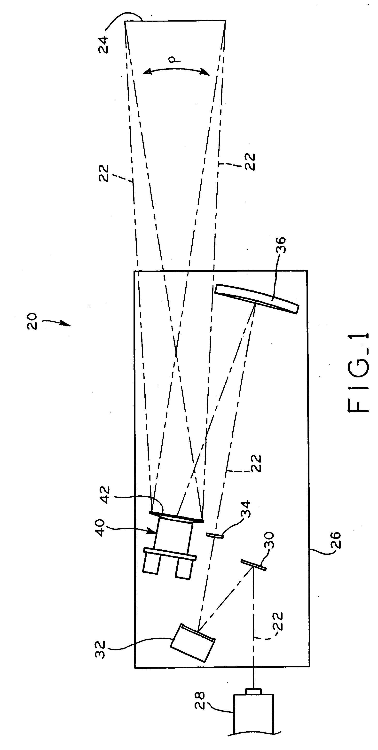
[0030] Referring to FIG. 1, the optical components of laser cutting system 20 are shown. In operation, laser cutting system 20 sweeps a cutting laser beam 22 along a cutting path P over the surface of a sheet of substrate material 24 to cut out individual pieces or articles from the substrate material 24. The optical components of laser cutting system 20 are shown in FIG. 1 in a top view, in which the components of laser cutting system 20 are arranged on a horizontal support surface 26 and the substrate material 24 is disposed vertically. However, the orientation of one or more of the components of laser cutting system 20, as well as the orientation of substrate material 24 may vary as desired; for example, the components of laser cutting system 20 may be arranged vertically, with substrate material 24 arranged horizontally.

[0031] Substrate material 24 may be any type of material which is to be cut, etched, or otherwise processed by laser cutting system 20, such as a sheet of paper...


PUM

PropertyMeasurementUnit
Responsivityaaaaaaaaaa

Abstract

A laser cutting system, including a steering mirror assembly for directing a laser beam through a predetermined cutting path along a workpiece or substrate material. The steering mirror assembly includes a base, and a mirror pivotally supported on the base by a flexure assembly which confines pivotal movement of the mirror about a vertical Y-axis and / or about a horizontal X-axis. A pair of electrical actuator assemblies include movable bobbin assemblies connected to the mirror by control rod flexures at locations on the mirror which are spaced 90° apart from one another. In operation, selective electrical energization of the actuator assemblies controls movement of the bobbin assemblies to pivot the mirror about the vertical Y-axis and / or about the horizontal X-axis throughout a number of angular orientations to thereby direct the laser beam through a predetermined cutting operation pattern along the substrate surface to cut materials from the substrate. The flexure arrangements which support the mirror on the base and which connect the bobbin assemblies to the mirror facilitate substantially frictionless movement of the bobbin assemblies and the mirror, which allows the mirror to pivot at high operational speeds during the cutting sequence.

Description

BACKGROUND OF THE INVENTION [0001] 1. Field of the Invention [0002] The present invention relates to a laser cutting system in which a laser beam is directed or steered through a predetermined cutting path along a substrate or workpiece to cut the substrate or workpiece. In particular, the present invention relates to a steering mirror assembly for directing the laser beam. [0003] 2. Description of the Related Art [0004] Blister card packaging is used to package and display small items at a retail sale location. One example of blister card packaging is the packaging used for small batteries, which generally includes a blister card including various display and informational graphics, to which a plastic bubble piece or “blister” is attached for containing the batteries. [0005] Typically, the foregoing types of packaging blister cards, display cards, clamshell inserts, etc., are printed on a large sheet of cardboard stock, and several different types of blister cards may optionally be...

Claims


Application Information

Patent Timeline
02 Mar 2006
Publication
US20060044655A1
IPC
G02B26/08
CPC
B23K26/10
Inventors
FISCHER, PAUL F.; MILLER, WARREN H.