Transmission device, transmission output control method, and radio communication device

a technology of transmission output and control method, which is applied in the direction of gain control, modulation, baseband system details, etc., can solve the problems of insufficient output level range and inability to meet the requirements, so as to reduce the size of the high-frequency power amplifier of the transmitter, wide output level range, and the effect of reducing the size of the radio communication apparatus

Inactive Publication Date: 2006-03-02
PANASONIC CORP
View PDF28 Cites 78 Cited by
  • Summary
  • Abstract
  • Description
  • Claims
  • Application Information

AI Technical Summary

Benefits of technology

[0011] The present invention is provided on such circumstances and an object of the invention is to provide a transmitter, a transmission output control method and a radio communication apparatus in which a wide output level range can be covered while high efficiency and good linearity can be obtained.
[0042] According to the transmitter, the transmission output control method and the radio communication apparatus according to the invention, there can be provided a transmitter, a transmission output control method and a radio communication apparatus in which a wide output level range can be covered while high efficiency and good linearity can be obtained.

Problems solved by technology

In the aforementioned transmitter, there was however the situation that the output level range could not be kept sufficiently wide because all the variable output level range of the power amplifier was covered with the saturation operating region in the input-output power characteristic.
Accordingly, there was the situation that the requirement could not be satisfied by means of covering all the output level range with the saturation operating region in the input-output power characteristic.

Method used


Image

  • Transmission device, transmission output control method, and radio communication device
  • Transmission device, transmission output control method, and radio communication device
  • Transmission device, transmission output control method, and radio communication device

Examples


first embodiment

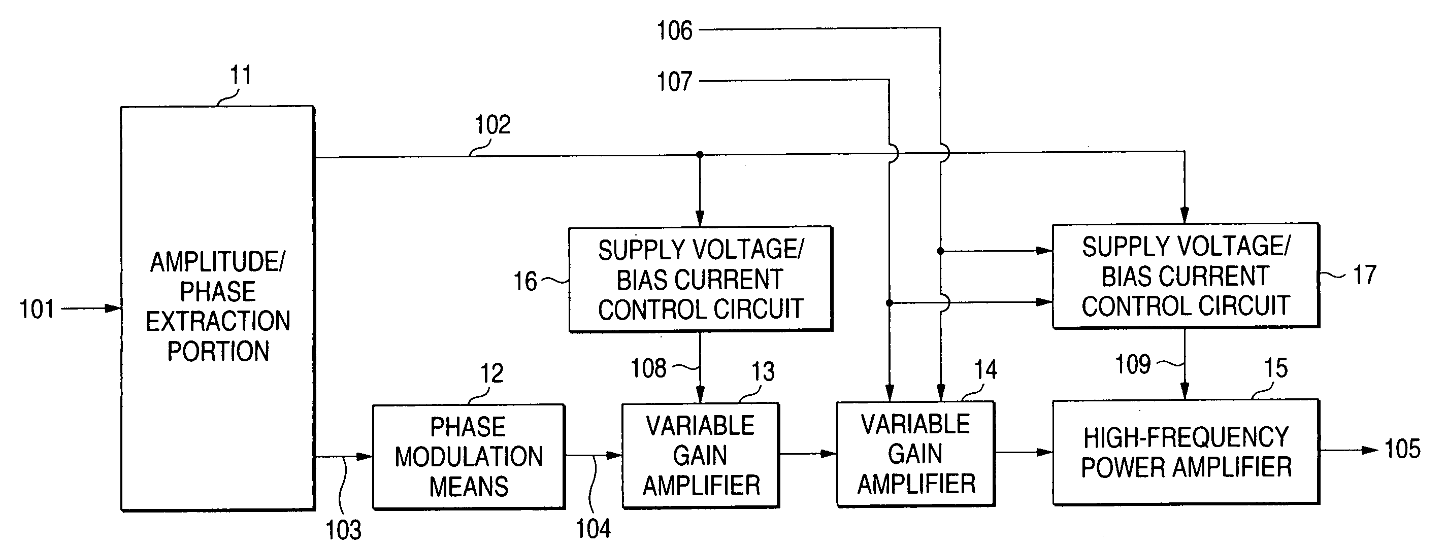
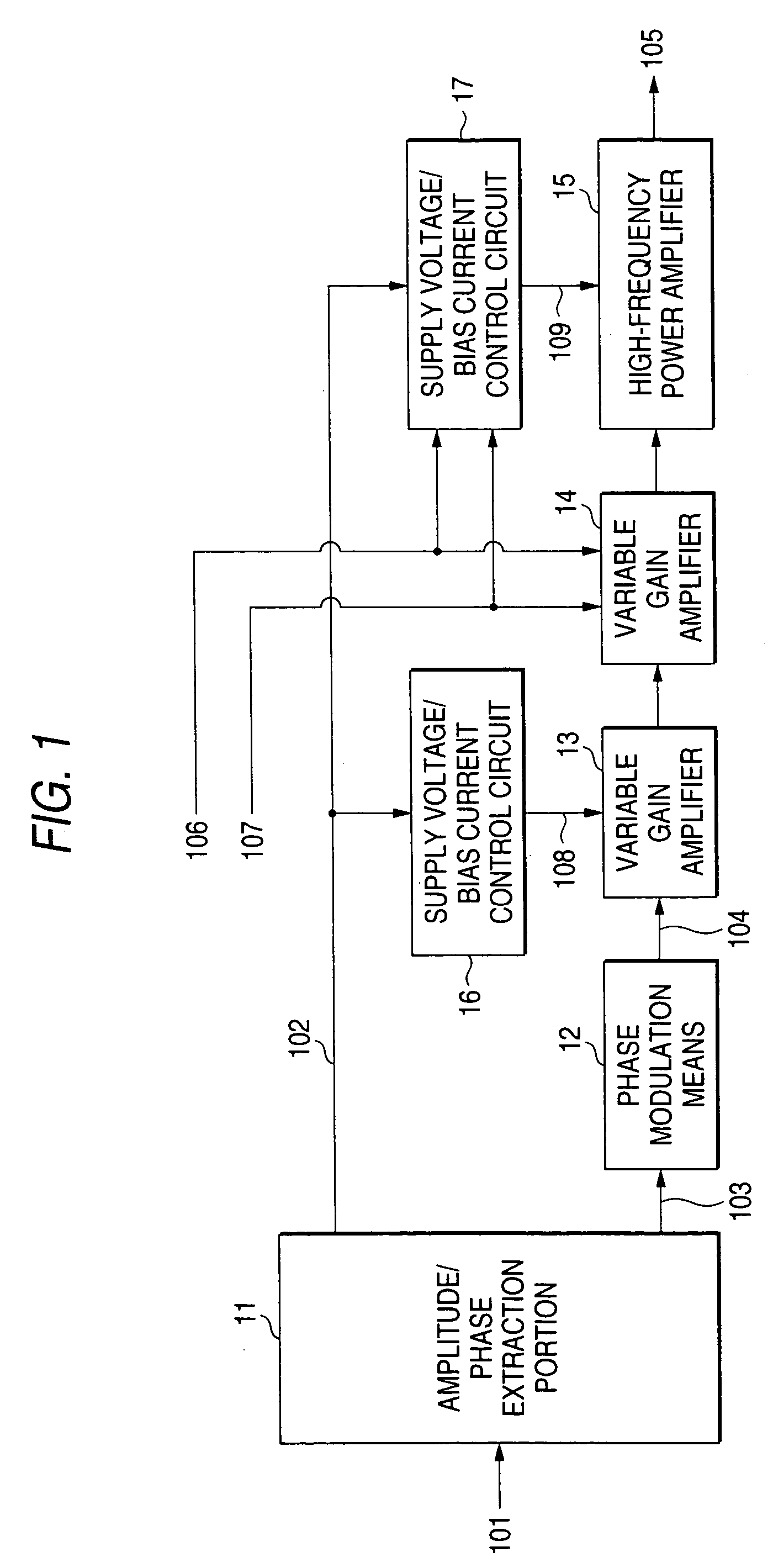
[0053]FIG. 1 is a schematic configuration diagram showing a transmitter for explaining a first embodiment of the invention. For example, the transmitter shown in FIG. 1 is a high-frequency transmitting portion of a mobile phone using a polar modulation method.

[0054] As shown in FIG. 1, the transmitter according to the first embodiment comprises: an amplitude / phase extraction portion 11 for separating an input baseband IQ signal 101 into a baseband amplitude signal 102 and a baseband phase signal 103 and outputting the signals 102 and 103; a phase modulation means 12 for applying phase modulation of a carrier signal on the baseband phase signal 103 and outputting a phase-modulated high-frequency signal 104; variable gain amplifiers 13 and 14 for amplifying the phase-modulated high-frequency signal 104; and a high-frequency power amplifier 15 for amplifying high-frequency power output from the variable gain amplifier 14 and outputting a transmitter signal 105.

[0055] The transmitter ...

second embodiment

[0096]FIG. 7 is a schematic configuration diagram showing a transmitter for explaining a second embodiment of the invention. In FIG. 7, parts overlapping those in FIG. 1 for description of the first embodiment are referred to by the same numerals.

[0097] As shown in FIG. 7, the transmitter according to the second embodiment of the invention comprises: an amplitude / phase extraction portion 11 for separating an input baseband IQ signal 101 into a baseband amplitude signal 102 and a baseband phase signal 103 and outputting the signals 102 and 103; a phase modulation means 12 for applying phase modulation of a carrier signal on the baseband phase signal 103 and outputting a phase-modulated high-frequency signal 104; a linear mixer 21 for applying amplitude modulation on the phase-modulated high-frequency signal 104; a variable gain amplifier 14 for amplifying the output of the mixer 21; a high-frequency power amplifier 15 for amplifying the output of the variable gain amplifier 14 as hi...

third embodiment

[0104]FIG. 8 is a schematic configuration diagram showing a transmitter for explaining a third embodiment of the invention. In FIG. 8, parts overlapping those in FIG. 1 for description of the first embodiment are referred to by the same numerals.

[0105] As shown in FIG. 8, the transmitter according to the third embodiment of the invention comprises: an amplitude extraction portion 31 for extracting a baseband amplitude signal 102 from an input baseband IQ signal 101 and outputting the baseband amplitude signal 102; a quadrature modulator 32 for performing phase modulation and amplitude modulation of a carrier from the baseband IQ signal 101; a variable gain amplifier 14 for amplifying the output of the quadrature modulator 32; a high-frequency power amplifier 15 for amplifying the output of the variable gain amplifier 14 as high-frequency power and outputting a transmitting signal 305; and a supply voltage / bias current control circuit 17 for generating a supply voltage 109 and a bia...


PUM


Abstract

An object of the invention is to provide a transmitter high in efficiency, good in linearity and capable of covering an output level in a wide range. Either linear operating mode or saturation operating mode is set as the operating mode of a high-frequency power amplifier (15) on the basis of an operating mode set signal (107). The gain of a variable gain amplifier (14) provided in front of the high-frequency power amplifier (15) and values of output voltage (109) and bias current supplied from a supply voltage / bias current control circuit (17) to the high-frequency power amplifier (15) are switched. The gain of the variable gain amplifier (14) in the saturation operating mode is formed so as to be higher by a predetermined value than that in the linear operating mode. Accordingly, the high-frequency power amplifier 15 operates in the designated operating mode, so that the output transmission power range can be widened.

Description

TECHNICAL FIELD [0001] The present invention relates to a variable output controllable transmitter, a transmission output control method and a radio communication apparatus using this transmitter. BACKGROUND ART [0002] Power efficiency and linearity in the transmitting function of a transmitter which can control its output variably are evaluated as indices for measuring the performance of the apparatus. The power efficiency and linearity in the transmitting function are most important indices for expressing the performance of the apparatus particularly in a high-frequency modulation transmitting apparatus such as a mobile phone. [0003] A so-called class A operation amplifier is widely used as an amplifier provided in a last stage of such a high-frequency modulation transmitting apparatus. The class A amplifier is low in distortion, that is, excellent in linearity but poor in power efficiency because the class A amplifier always spends electric power resulting from a DC bias componen...

Claims


Application Information

Patent Timeline
Patent Type & Authority Applications(United States)
IPC IPC(8): H04B1/04H01Q11/12H03F3/24H03F3/189H03G3/00H03G3/10H03G3/30
CPCH03F1/0222H03F3/189H03G3/004H04B2001/045H03G2201/103H03G2201/307H03G2201/40H03G3/3042H03F1/02H03F3/24
Inventor HARA, YOSHIHIROARAYASHIKI, MAMORU
Owner PANASONIC CORP
Why Eureka
Try Eureka