Reduced wear throttle valve bearing

a technology of bearings and throttle valves, applied in the direction of machines/engines, manufacturing tools, other domestic objects, etc., can solve the problems of excessive radial wear and achieve the effect of reducing friction resistance and preventing premature wear

Inactive Publication Date: 2006-03-09
ROBERT BOSCH GMBH
View PDF5 Cites 16 Cited by
  • Summary
  • Abstract
  • Description
  • Claims
  • Application Information

AI Technical Summary

Benefits of technology

[0008] In order to reduce frictional resistances and prevent premature wear at bearing locations between a throttle valve housing and a throttle valve shaft, according to the present invention, bearing bushes are installed on the throttle valve shaft and / or in the throttle housing. The bearing bushes can be inserted in a non-rotating fashion into the previously molded housing part of the throttle unit so that the throttle valve shaft parts injection molded onto the preferably curved valve flap part can rotate in the housing part. Alternatively, it is possible to insert the bearing bushes into the previously molded housing part in such a way that the bearing bushes can rotate in relation to the previously molded housing part and the throttle valve parts of the preferably curved valve flap part are injection molded in a non-rotating fashion into the bearing bushes that have been previously inserted into the wall of the previously molded housing part.

Problems solved by technology

With high RZ values, the circumferential surface of the bearing bush would act in a material-removing manner on the plastic, which would result in an excessively high degree of wear in the radial direction as operation time increased.

Method used


Image

  • Reduced wear throttle valve bearing
  • Reduced wear throttle valve bearing
  • Reduced wear throttle valve bearing

Examples


Embodiment Construction

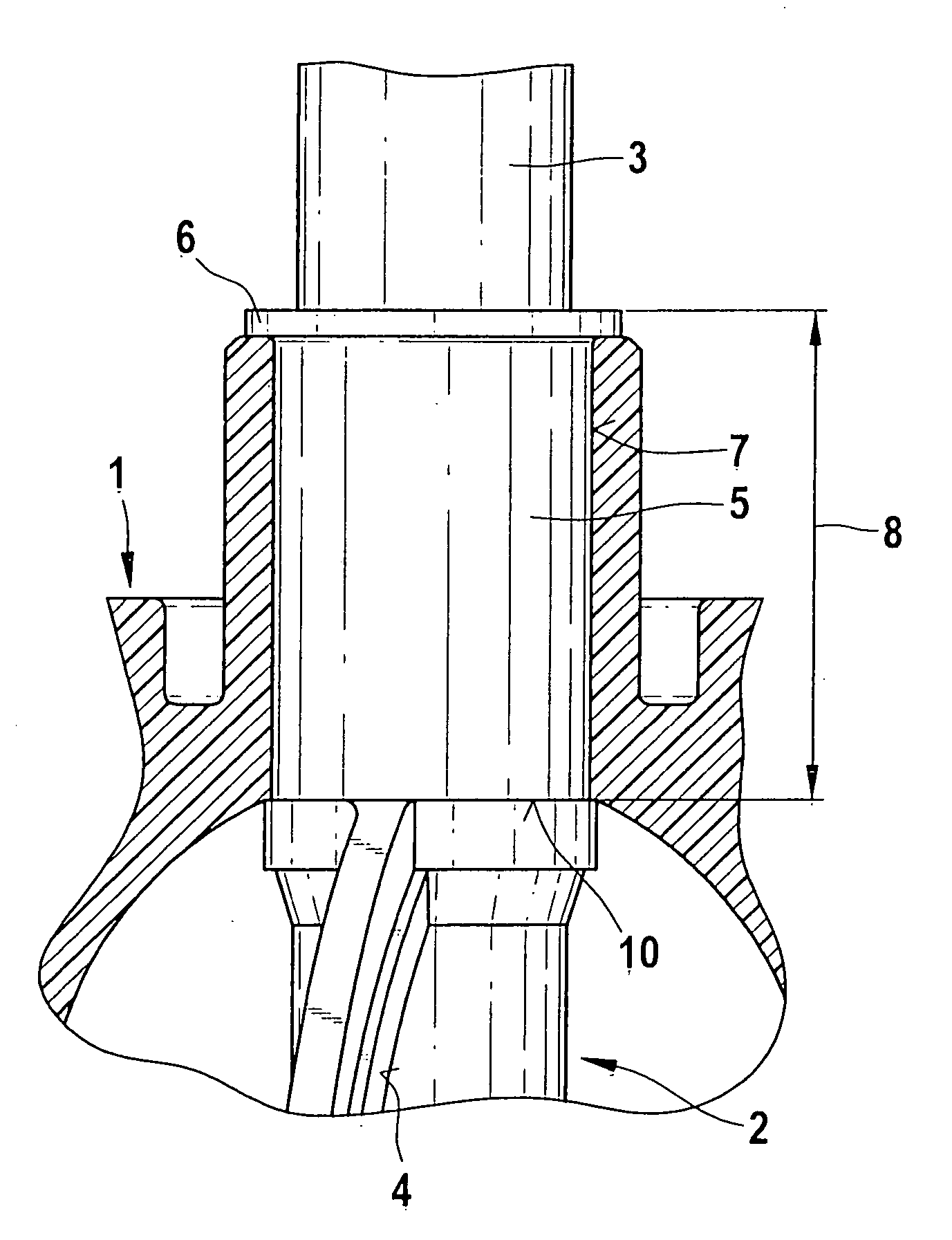
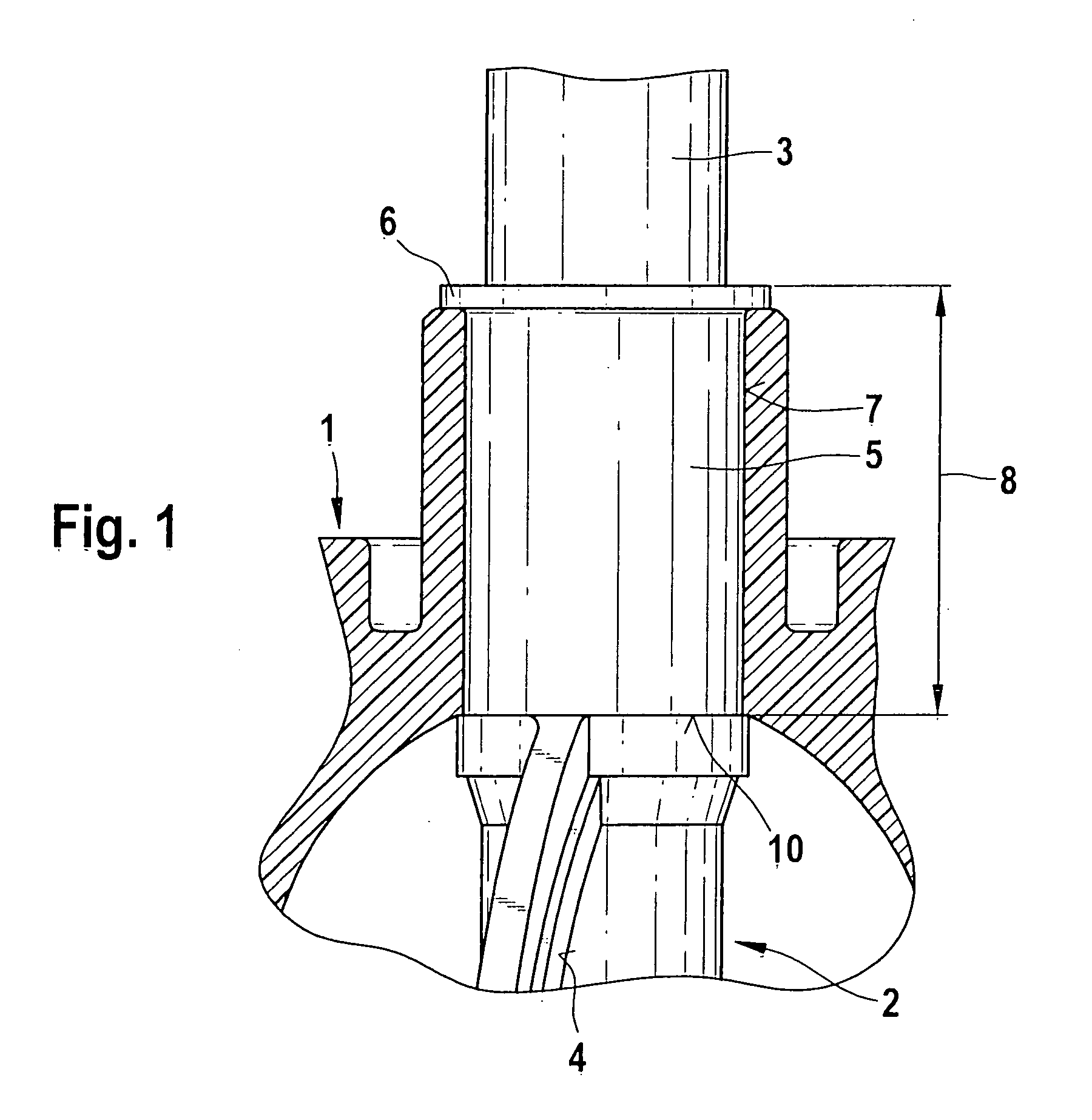
[0017]FIG. 1 shows a bearing bush that is embodied with a first axial length, is accommodated in a throttle valve housing, and encompasses a throttle valve shaft. The throttle valve housing is manufactured out of a plastic material such as PPS (polyphenylene sulfide) by means of the injection molding process. The throttle valve housing 1 contains a throttle valve 2 that can rotate around a valve shaft 3. The valve shaft 3 of the throttle valve 2 supports the throttle valve flap 4, which opens or closes a gas passage opening in accordance with the pivoting position of the throttle valve flap 4.

[0018] The throttle valve housing 1 accommodates a bearing bush 5 having a shoulder 6 that extends outward in the depiction according to FIG. 1. The reference numeral 7 identifies a circumferential surface of the bearing bush 5, which is embodied with an axial length 8. The circumferential surface 7 of the bearing bush 5 constitutes an axial contact surface 10 of the bearing bush 5 in relation...


PUM

PropertyMeasurementUnit
radiusaaaaaaaaaa
temperatureaaaaaaaaaa

Abstract

A method for optimizing the friction, wear, and function of an injection-molded throttle valve unit, including a throttle valve housing and a throttle valve that can move in relation to it. The throttle valve housing is injection molded out of a first plastic material inside a first cavity, then transferred to a second cavity. Bearing bushes are inserted into the throttle valve housing to constitute a hard/hard friction pairing between the bearing bushes and the throttle valve housing; either the bearing bushes are inserted into the throttle valve housing in a non-rotating fashion and the valve shaft rotates in relation to the bearing bushes or the bearing bushes rotate in relation to the throttle valve housing. The bearing bushes are preferably manufactured out of a metallic material and remain dimensionally stable when subjected to the injection pressure.

Description

CROSS-REFERENCE TO RELATED APPLICATIONS [0001] This application is based on German Patent Application 10 2004 043 427.1 filed Sep. 6, 2004, upon which priority is claimed. BACKGROUND OF THE INVENTION [0002] 1. Field of the Invention [0003] In the automotive field, throttle valve units are increasingly produced in large batches in the form of plastic injection molded components. For example, such throttle valve units are valves injection molded into the valve housing together with the injection molding process that produces the housing. The throttle valve units that are used in the automotive field are subjected to temperatures between −40° C. and 140° C. so that care must be taken to assure the operational reliability of the formed parts in this temperature range, specifically with regard to gap widths that can be achieved in the injection molding process. [0004] 2. Description of the Prior Art [0005] EP 0 482 272 B1 relates to a valve unit, disclosing a valve device and a method fo...

Claims


Application Information

Patent Timeline
Patent Type & Authority Applications(United States)
IPC IPC(8): B21K1/20
CPCF02D9/106Y10T29/4998Y10T29/49412Y10T29/49298Y10T29/49307Y10T29/49314
Inventor LORENZ, CHRISTIANZOELCH, ROLANDSCHONDER, FRANK
Owner ROBERT BOSCH GMBH
Why Eureka
Try Eureka