Superstructure of engine

Active Publication Date: 2006-03-09
YANMAR CO LTD
View PDF8 Cites 4 Cited by
  • Summary
  • Abstract
  • Description
  • Claims
  • Application Information

AI Technical Summary

Benefits of technology

[0029] According to the present invention, the main body is formed by a two-part mold, and a suction hole provided in the main body is formed perpendicular to draft direction of the mold by adhering two molds with each other. Accordingly, the main body can be formed easily by aluminum die casting. The suction port can be formed simultaneously with the main body by the mold, whereby the boring work is omitted so as to reduce the cost.
[0030] According to the present invention, a suction hole of intake pipe is formed to be an extension of the intake port of the cylinder head. Accordingly, the air flow from the air cleaner through the suction hole to the intake port is smooth and turbulence is prevented from being generated in the suction passage so as to supply air from the air cleaner to the intake port stably. Accordingly, resistance of air, introduced from the intake port, in the suction passage is made small so as to promote swirls formed at the time that the air flows from the valve hole of the intake valve into the cylinder.
[0031] According to the present invention, with regard to a superstructure of an engine comprising a breather in an upper portion of a rocker arm chamber, a baffle is provided around an air hole of the breather in the rocker arm casing, and a slit is provided so as to open a lower portion of the baffle. Accordingly, even if lubricating oil accumulated in the rocker arm chamber reaches the lower end of the baffle, air can be vented through the slit provided in the baffle, thereby preventing the lubricating oil accumulated in the rocker arm chamber from sucked through the air hole. Namely, unless the rocker arm chamber is filled with lubricating oil, the lubricating oil is prevented from entering through the air hole. Accordingly, the generation of exhaust emission, caused by the lubricating oil, is prevented, thereby improving exhaust ability. The slit can be formed easily, whereby the above-mentioned effect can be obtained with a simple construction without providing a cavity by drilling instead of the slit.
[0032] According to the present invention, a reflux passage of the breather and a starting adjuvant injection passage are constructed integrally with a rocker arm casing of

Problems solved by technology

However, as the above mentioned, in the case of introducing outer air directly through the air intake part provided in the air cleaner, if the engine is arranged in a closed cabinet, the heat of the engine itself may prevent the introduction of cool air.
Furthermore, with regard to the above-mentioned art disclosed in the Japanese Utility Model Laid Open Gazette Hei. 5-50061, the air cooling mechanism and the air cleaner are connected to each other through the duct, whereby part number increases and the cost increases.
However, with regard to the air cleaner attached to the intake port provided in the cylinder head of the engine through the intake pipe, as disclosed in the Japanese Patent Laid Open Gazette 2001-73897 for example, the air cleaner and the intake pipe are constructed separately, whereby part number increases and the cost increases.
Furthermore, the air cleaner is attached to the cylinder head through the intake pipe, therefore it is difficult to make the constr

Method used


Image

  • Superstructure of engine
  • Superstructure of engine
  • Superstructure of engine

Examples


Embodiment Construction

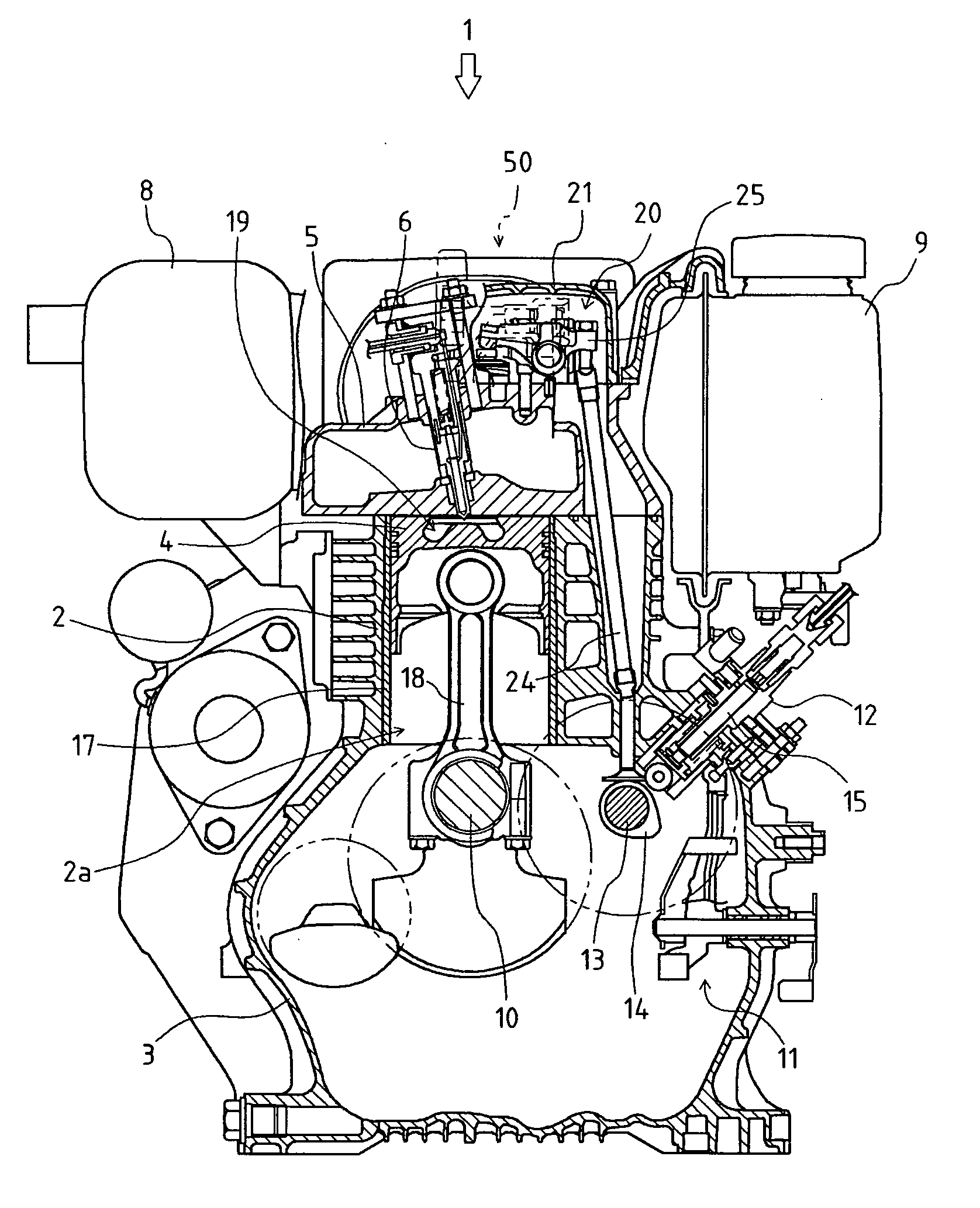
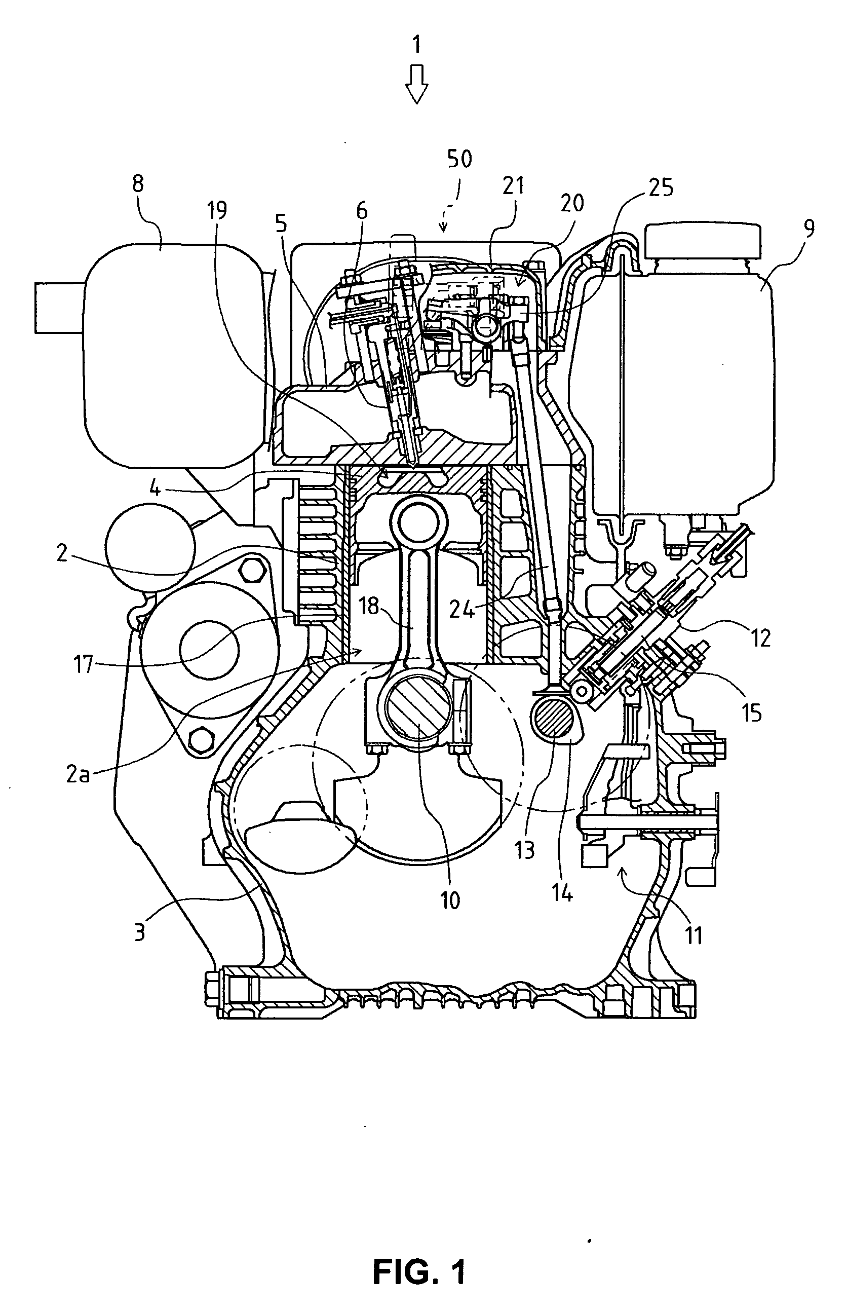
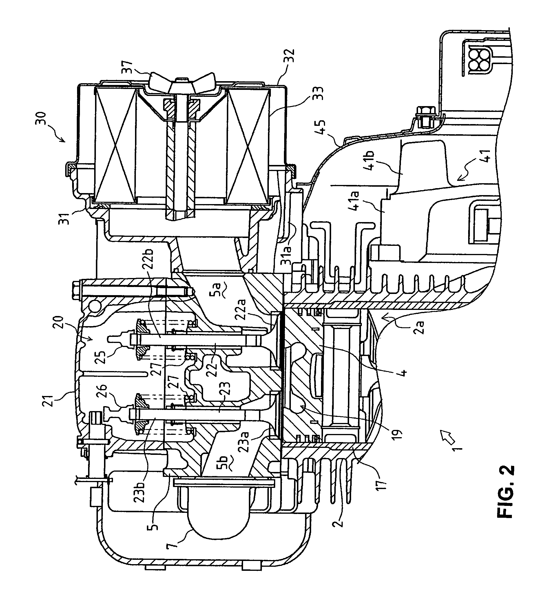
[0049] Firstly, explanation will be given on the entire construction of an engine 1 according to FIGS. 1 to 3.

[0050] The upper portion of the main body of the engine 1 comprises a cylinder block 2 and the lower portion thereof comprised a crankcase 3. A cylinder 2a is formed vertically at the center of the cylinder block 2, and a piston 4 is vertically slidably housed in a cylinder liner 17 in the cylinder 2a. Below the cylinder block 2, a crankshaft 10 is pivotally supported longitudinally by the crankcase 3, and the crankshaft 10 and the piston 4 are connected to each other through a connecting rod 18.

[0051] The upper portion of the cylinder block 2 is covered by a cylinder head 5. In the cylinder head 5, an intake valve 22, an exhaust valve 23 and a fuel injection nozzle 6 are arranged. A space above the cylinder head 5 is covered by a rocker arm casing 21 so as to construct a rocker arm chamber 20. A muffler 8 is arranged at one of sides of the rocker arm casing 21, and a fuel...


PUM


Abstract

With regard to a construction that a fan 41 is provided at one side of an engine 1 and covered by a fan casing 45, and an air cleaner 30 is arranged near the fan casing 45 and at a side of a cylinder head 5 on which an intake port 5a is disposed, a suction port 31a communicated with the inside of the fan casing 45 is provided in a main body 31 of the air cleaner 30. A barrier 46 is provided at a position facing to the suction port 31a in the air cleaner 30. A wall standing toward the fan casing 45 and the cylinder head 5 is formed on the outer surface of the main body 31 of the air cleaner 30. An air intake part is provided on one of side surfaces of a cover body 32 of the air cleaner 30 and the cover body 32 is constructed to be an equilateral polygon. An intake pipe 31k communicating the air cleaner 30 with the intake port 5a of the cylinder head 5 is constructed integrally with a main body 31 of the air cleaner 30.

Description

CROSS-REFERENCE TO RELATED APPLICATION [0001] The present application is a Continuation of PCT Application No. PCT / JP2004 / 001671, filed Feb. 16, 2004, which is incorporated in its entirety herein by reference thereto.BACKGROUND OF THE INVENTION [0002] 1. Field of the Invention [0003] The present invention relates to a superstructure of an engine. In detail, the present invention relates to a construction of an air cleaner cleaning air going to a combustion chamber of the engine, a construction of breather provided in an upper portion of a rocker arm casing, and a construction from the air cleaner and breather to an air intake part in a cylinder head. [0004] 2. Background Art [0005] Conventionally, an air cleaner cleaning air going to a combustion chamber is provided in an upper portion or the like of an engine, and the air cleaner introduces and cleans outside air, and the cleaned air is supplied to the combustion chamber as combustion air. [0006] With regard to the air cleaner, an ...

Claims


Application Information

Patent Timeline
IPC IPC(8): F02M35/06F02M25/06F02F1/42F01M13/04F01P1/02F01P5/02F02M35/024F02M35/04
CPCF01M13/0416F01P1/02F02M35/06F02M35/024F02M35/04F01P5/02F01M13/02F01P5/06F02M25/06
Inventor SAMO, JUNICHISHIOTA, KATSUYUKIKANAZU, YASUHIRONISHIMURA, SHINJISAGARA, MASASHI
Owner YANMAR CO LTD
Why Eureka
Try Eureka