Magnetron assembly

a technology of magnet assembly and assembly plate, which is applied in the direction of electrolysis components, vacuum evaporation coatings, coatings, etc., can solve the problems of shortening the life of the assembly, stray currents or eddy currents, and changing the current amplitudes of the load side of the power supply, so as to reduce or eliminate the degradation of bearings, prevent current flow, and reduce or eliminate the effect of bearing degradation

Inactive Publication Date: 2006-03-09
APPLIED MATERIALS INC
View PDF40 Cites 26 Cited by
  • Summary
  • Abstract
  • Description
  • Claims
  • Application Information

AI Technical Summary

Benefits of technology

[0014] A still further embodiment is to provide a bearing with a conductive (rather than a conventional non-conductive) grease between the bearing race and the bearing balls or rollers. In conventional bearings with conventional dielectric (non-conductive) grease, to the extent current flows through the bearings, arcing occurs as the current flows from the race to the ball or roller across the dielectric grease. This arcing can cause pitting, fluting or other bearing degradation. By making the grease conductive, arcing and thus bearing degradation is eliminated or substantially reduced.
[0015] Accordingly, the solution to bearing degradation in accordance with the present invention is to either preclude the flow of current through the bearing structure by the use of non-conductive materials or by providing a low resistance current flow path in close association with the bearings or allow the current to flow through the bearings in a way which prevents arcing between the bearing race and the bearing balls or rollers.
[0016] Accordingly, it is an object of the present invention to reduce or eliminate bearing degradation in a rotary magnetron sputtering system.

Problems solved by technology

When these systems are implemented, they can result in rapidly changing current amplitudes on the load side of the power supply.
It is believed that these rapidly changing currents induce stray currents or eddy currents in the magnetron assembly.
The current loops formed by these stray currents can cause significant damage to bearings in the magnetron assembly and can shorten the life of the assembly.
With this structure, current is substantially prevented from passing through the bearing (and thus arcing between the race and the ball or roller) where it can cause pitting, fluting or other degradation of the bearing.

Method used


Image

  • Magnetron assembly
  • Magnetron assembly
  • Magnetron assembly

Examples


Embodiment Construction

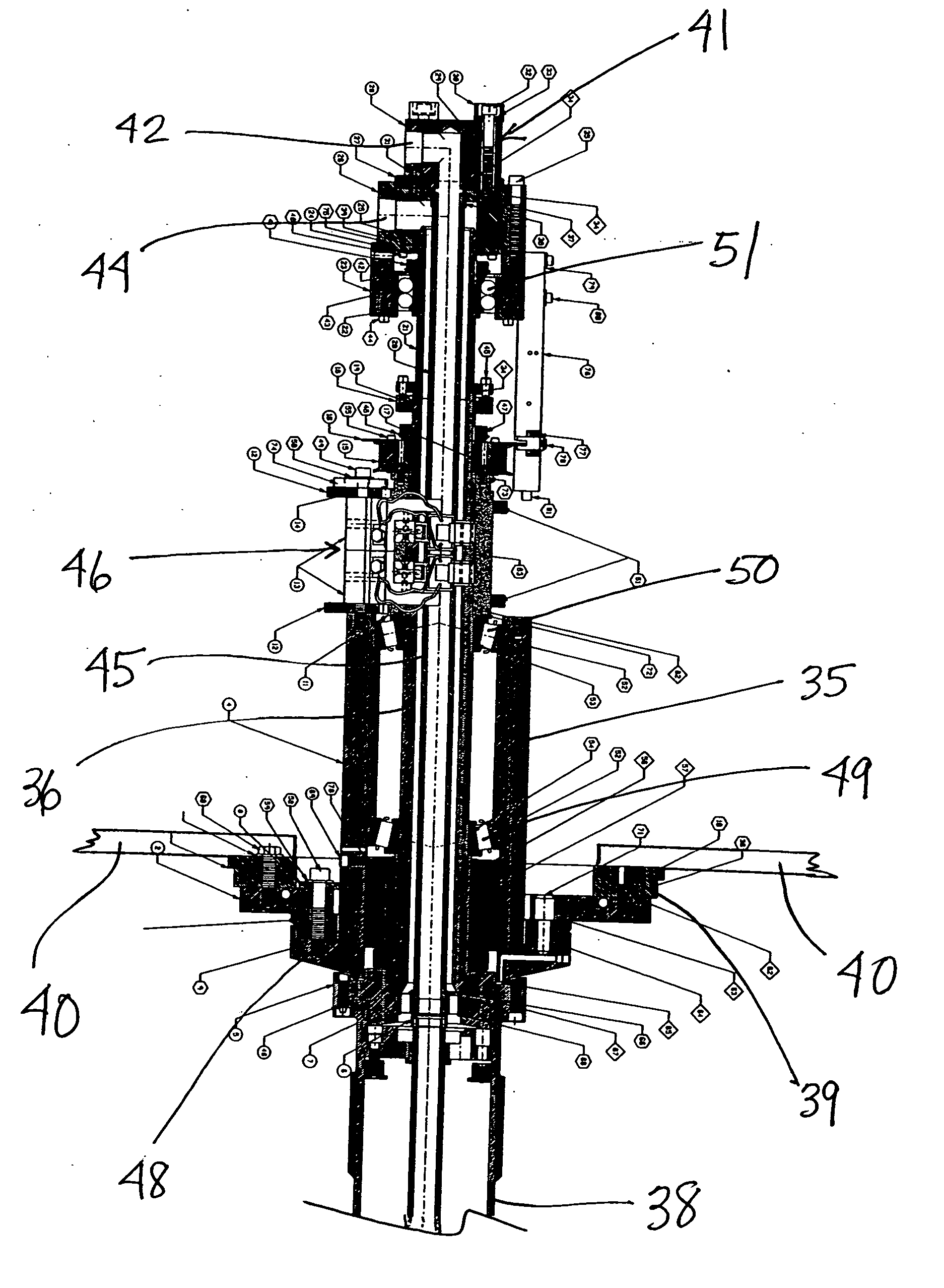
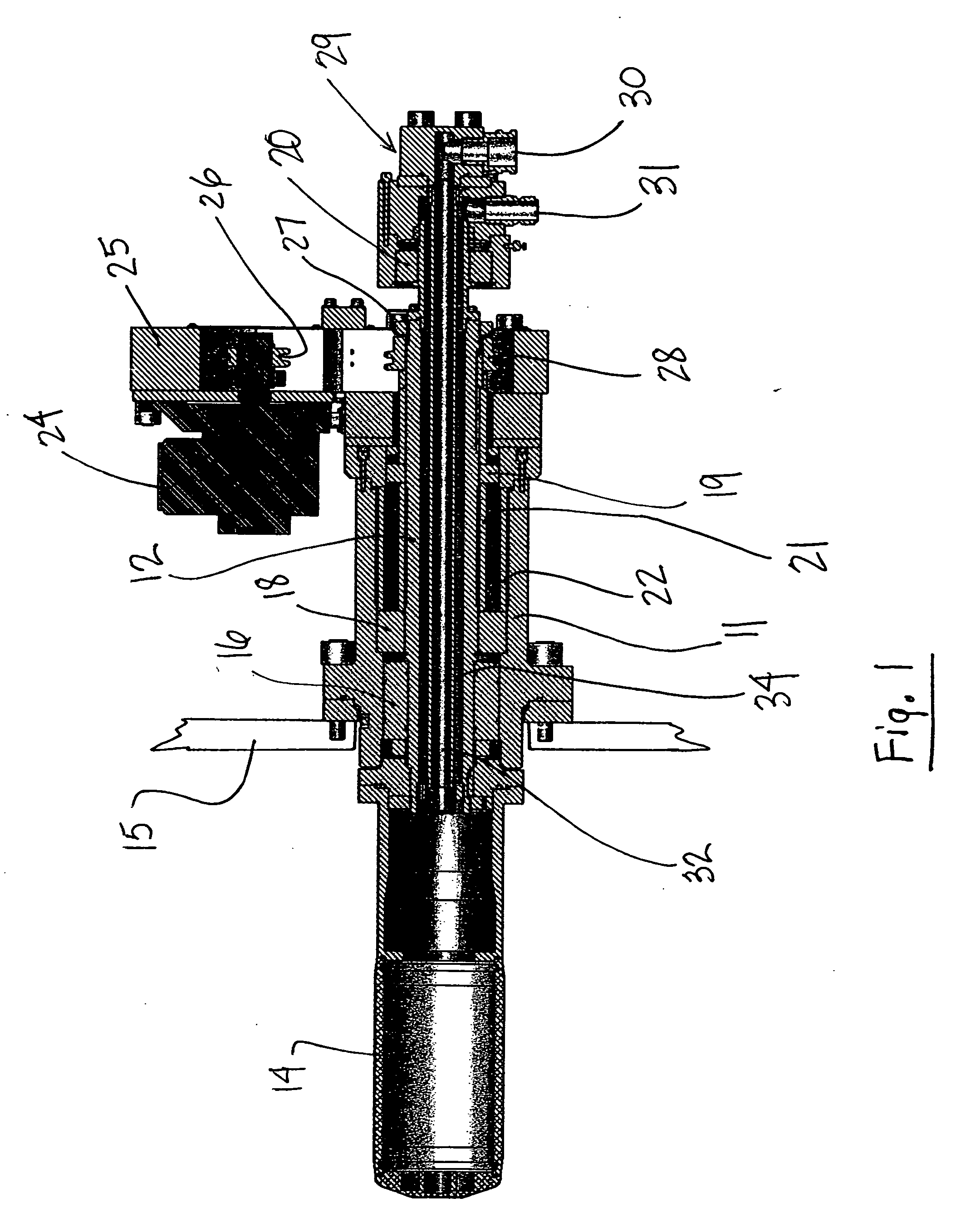
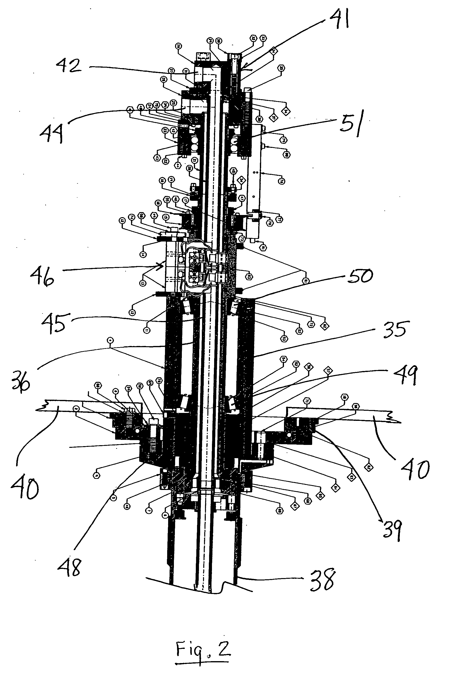
[0030] The present invention relates generally to a rotary magnetron sputtering or cathode assembly and more specifically to such an assembly incorporating means for preventing or substantially reducing bearing degradation and thus lengthening the bearing and assembly life. Such means includes means for either electrically isolating the various bearings between the drive shaft and housing to interrupt or substantially reduce any stray or eddy current flow through the bearing or providing a conductive bearing grease between the race and bearing member to eliminate or substantially reduce any arcing resulting from current flow through the bearing. Such means may be utilized by itself or in combination with means for addressing the inductive heating issue by water cooling the housing and / or bearing seal.

[0031] The various bearing configurations in accordance with the present invention have particular application to alternating current (AC) rotary magnetron sputtering assemblies. Examp...


PUM

PropertyMeasurementUnit
electrically conductiveaaaaaaaaaa
electrical currentaaaaaaaaaa
electrically non-conductiveaaaaaaaaaa

Abstract

A rotating magnetron assembly having a structure to reduce bearing degradation by substantially preventing the flow of current through the bearing using non-conductive materials or providing a low resistance current flow path or by allowing current to flow through the bearing in a way which prevents arcing between the various bearing components.

Description

BACKGROUND OF THE INVENTION [0001] 1. Field of the Invention [0002] The present invention relates generally to an improved magnetron assembly and more specifically to a rotating magnetron assembly with means for reducing or eliminating bearing deterioration and degradation. The invention also relates to an improved bearing structure for use in a rotating magnetron assembly. [0003] 2. Description of the Prior Art [0004] A rotating cathode or magnetron assembly includes a vacuum sputtering chamber, a rotatable target within the vacuum chamber and a drive shaft for rotating the target. The drive shaft is supported in a housing by a plurality of bearings and the vacuum chamber is sealed from the ambient atmosphere. A seal / bearing combination such as a ferro fluidic seal which includes both a bearing component and a seal component is positioned between the drive shaft and the housing to form and maintain the seal between the vacuum chamber and the ambient atmosphere. [0005] Power to the ...

Claims


Application Information

Patent Timeline
Patent Type & Authority Applications(United States)
IPC IPC(8): C23C14/00
CPCH01J37/3405H01J2237/0209H01J2237/0206H01J37/3455
Inventor MATUSKA, NEAL W.ANDERSON, JOEL T.TAYLOR, CLIFFORD L.GERMAN, JOHN R.
Owner APPLIED MATERIALS INC
Why Eureka
Try Eureka