
Mechanical density altitude compensation device for helicopter tail rotors

Inactive Publication Date: 2006-03-09
WILKERSON DARRELL WADE
View PDF10 Cites 4 Cited by
  • Summary
  • Abstract
  • Description
  • Claims
  • Application Information

AI Technical Summary

Benefits of technology

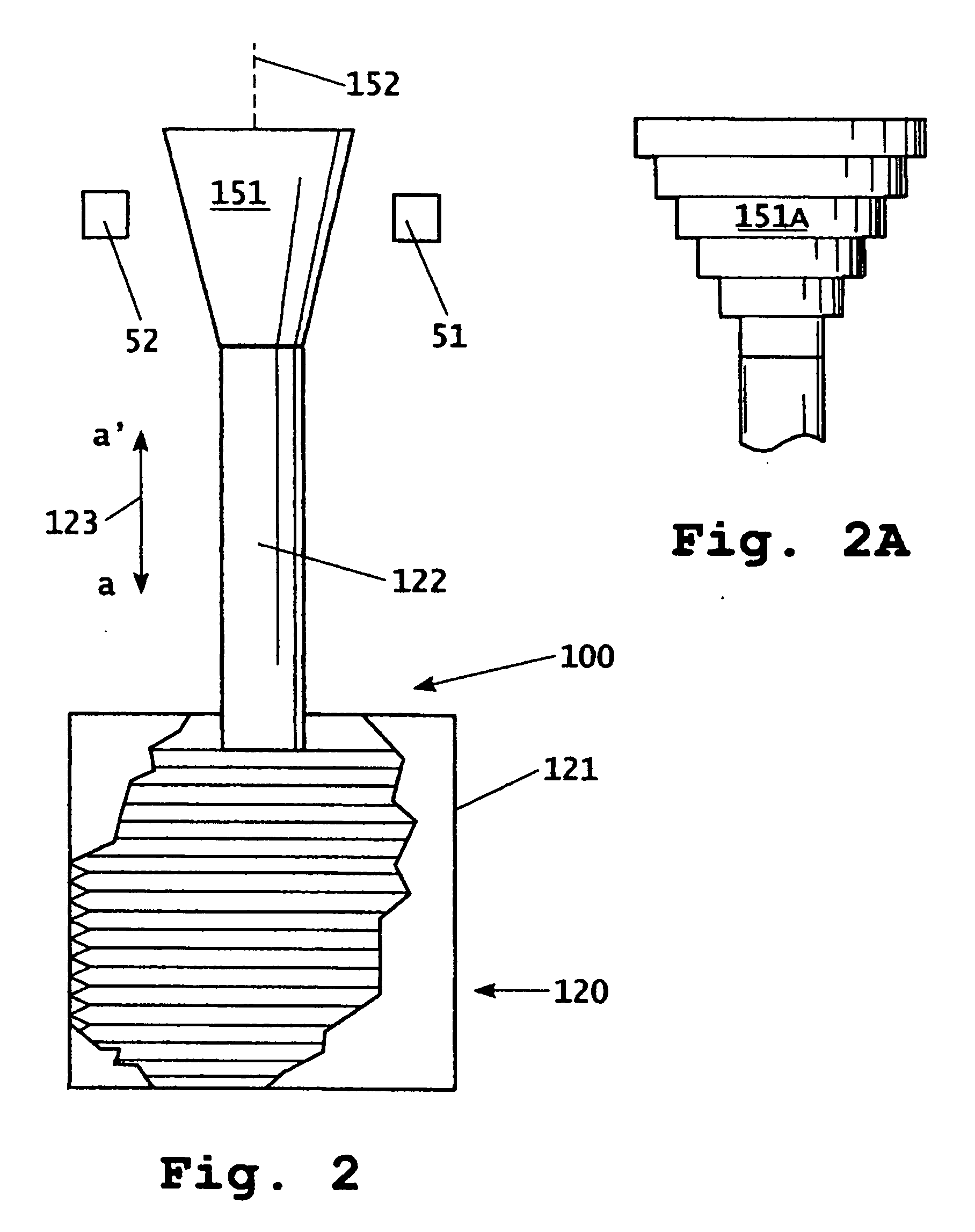
[0014] The invention provides a simple, mechanical apparatus for controlling the range of available tail rotor pitch in response to changes in ambient air conditions that affect air density. Those ambient air conditions may include ambient air pressure, ambient air temperature and, to a lesser extent, ambient air moisture content, all of which affect air density.
[0016] In its usual configuration, the mechanism of the invention permits the maximum pitch to which the tail rotor can be adjusted to increase with decreasing air density. This allows the tail rotor to assume a greater pitch under lower air density operating conditions, thereby increasing the thrust that can be generated by the tail rotor under the lower air density conditions. At higher air density conditions, the maximum available pitch that can be imparted to the tail rotor is more limited by the mechanism of the invention. This has the effect of limiting the maximum thrust that can be generated by the tail rotor at the higher air density conditions and helps to prevent over-thrust at higher air density conditions. The ability to vary the range of allowable tail rotor pitch with air density improves control over the vehicle under low air density conditions without over-thrusting during higher air density conditions.

Problems solved by technology

A helicopter tail rotor works less efficiently at higher density altitudes.
The problem, however, with simply changing tail rotor operating parameters to provide the tail rotor authority needed at higher density altitudes is that these changes often cause too much thrust to be produced at lower density altitudes.
Too much thrust can overload the helicopter airframe and drive train components as well as the tail rotor flight controls.
Because of the operation of the proximity sensors, the Halwes apparatus is not as responsive and accurate as desired.

Method used


Image

  • Mechanical density altitude compensation device for helicopter tail rotors
  • Mechanical density altitude compensation device for helicopter tail rotors
  • Mechanical density altitude compensation device for helicopter tail rotors

Examples


Embodiment Construction

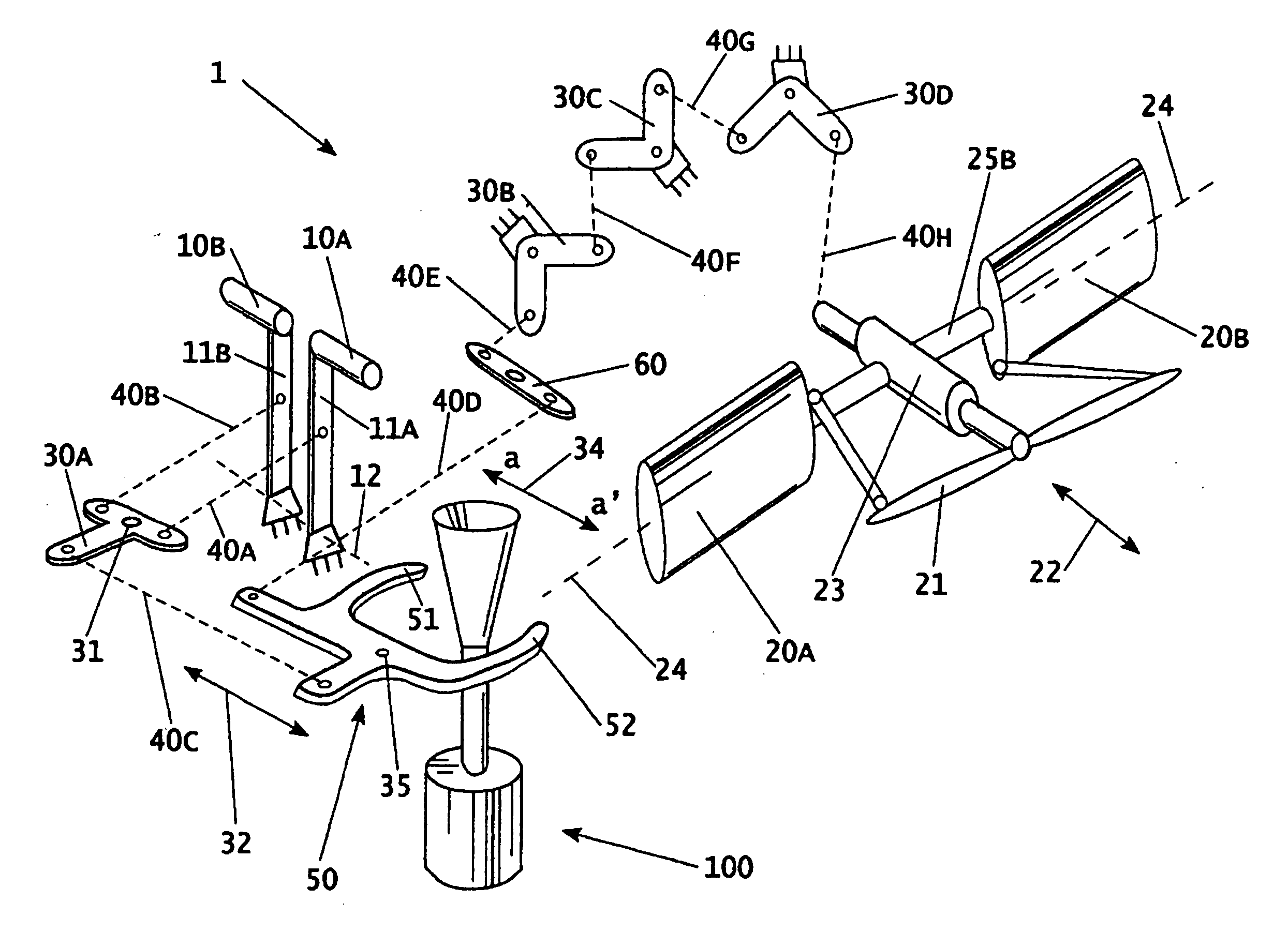
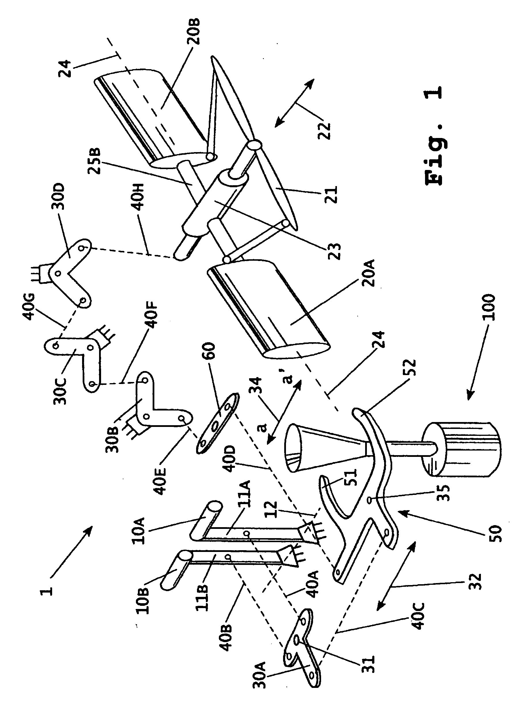
[0029] In FIG. 1, helicopter tail rotor pitch-range control mechanism 1 contains a helicopter tail rotor pitch-change control system that includes control pedals 10A and 10B and a series of linkage members that communicate with rotors 20A and 20B. Pedals 10A and 10B are mounted on cranks 11A and 11B, respectively. When pedals 10A and 10B are depressed, cranks 11A and 11B move about axis 12, actuating a series of linkage members that move lever 21 inwardly or outwardly in the direction shown by double-headed arrow 22. Lever 21 connects to rotor hubs 25A and 25B or directly to rotors 20A and 20B. The inward and outward movement of lever 21 causes rotor hubs 25A and 25B to rotate about axis 24, thereby changing the pitch of rotors 20A and 20B. As shown, the linkage members within the helicopter tail rotor pitch-change control system also include components such as linkage members 30A-D and 60, linkage member 50, and push / pull tubes 40A-H. However, the type and arrangement of the variou...


PUM


Abstract

A helicopter tail rotor pitch-range altering device is disclosed. The device is incorporated into the existing helicopter tail rotor pitch-change control system of a helicopter and automatically alters the amount of tail rotor pitch available from the helicopter's tail rotor pitch-change control system based on changes in density altitude. The device comprises an ambient air density sensing device and a movable member located within or located in proximity to the helicopter tail rotor pitch-change flight control system. In one embodiment, a sealed bellows is connected directly to a movable member within the helicopter tail rotor pitch-change control system. As density altitude changes, the length of the bellows changes accordingly and moves the movable member within the helicopter's tail rotor pitch-change control system providing a varying tail rotor pitch-range based on density altitude.

Description

CROSS-REFERENCE TO RELATED APPLICATIONS [0001] This application claims benefit of U.S. Provisional Application No. 60 / 603,692, filed Aug. 23, 2004.BACKGROUND OF THE INVENTION [0002] This invention relates to a device for altering the available pitch-range of a helicopter tail rotor based on changes in air density or changes in components of air density such as ambient air pressure, ambient air temperature or ambient air moisture content. [0003] Most common rotor wing aircraft (helicopters) have a rotor system that consists of a main rotor and a tail rotor. The main rotor provides lift and translational force. The tail rotor provides sideward thrust that counteracts the torque affects induced on the helicopter by the driving of the main rotor. The sideward thrust not only counteracts the main rotor torque, it also provides yaw control or directional control for the helicopter. The pilot can vary the amount of sideward thrust put out by the tail rotor through controls, which are typic...

Claims


Application Information

Patent Timeline
IPC IPC(8): B64C27/54
CPCB64C27/82B64C13/16
Inventor WILKERSON, DARRELL WADE
Owner WILKERSON DARRELL WADE
Learn More