
Method of embedding semiconductor chip in support plate and embedded structure thereof

Active Publication Date: 2006-03-09
PHOENIX PRECISION TECH CORP
View PDF4 Cites 35 Cited by
  • Summary
  • Abstract
  • Description
  • Claims
  • Application Information

AI Technical Summary

Benefits of technology

[0009] In light of the above prior-art drawbacks, a primary objective of the present invention is to provide a method of embedding a semiconductor chip in a support plate and an embedded structure thereof, so as to effectively fix the semiconductor chip in place in the support plate.
[0010] Another objective of the present invention is to provide a method of embedding a semiconductor chip in a support plate and an embedded structure thereof, which can maintain flatness and consistency of the semiconductor chip being embedded in an opening of the support plate.
[0011] Still another objective of the present invention is to provide a method of embedding a semiconductor chip in a support plate and an embedded structure thereof, which can avoid an alignment error between the semiconductor chip and an opening of the support plate as well as difficulty in continuing subsequent fabrication processes.

Problems solved by technology

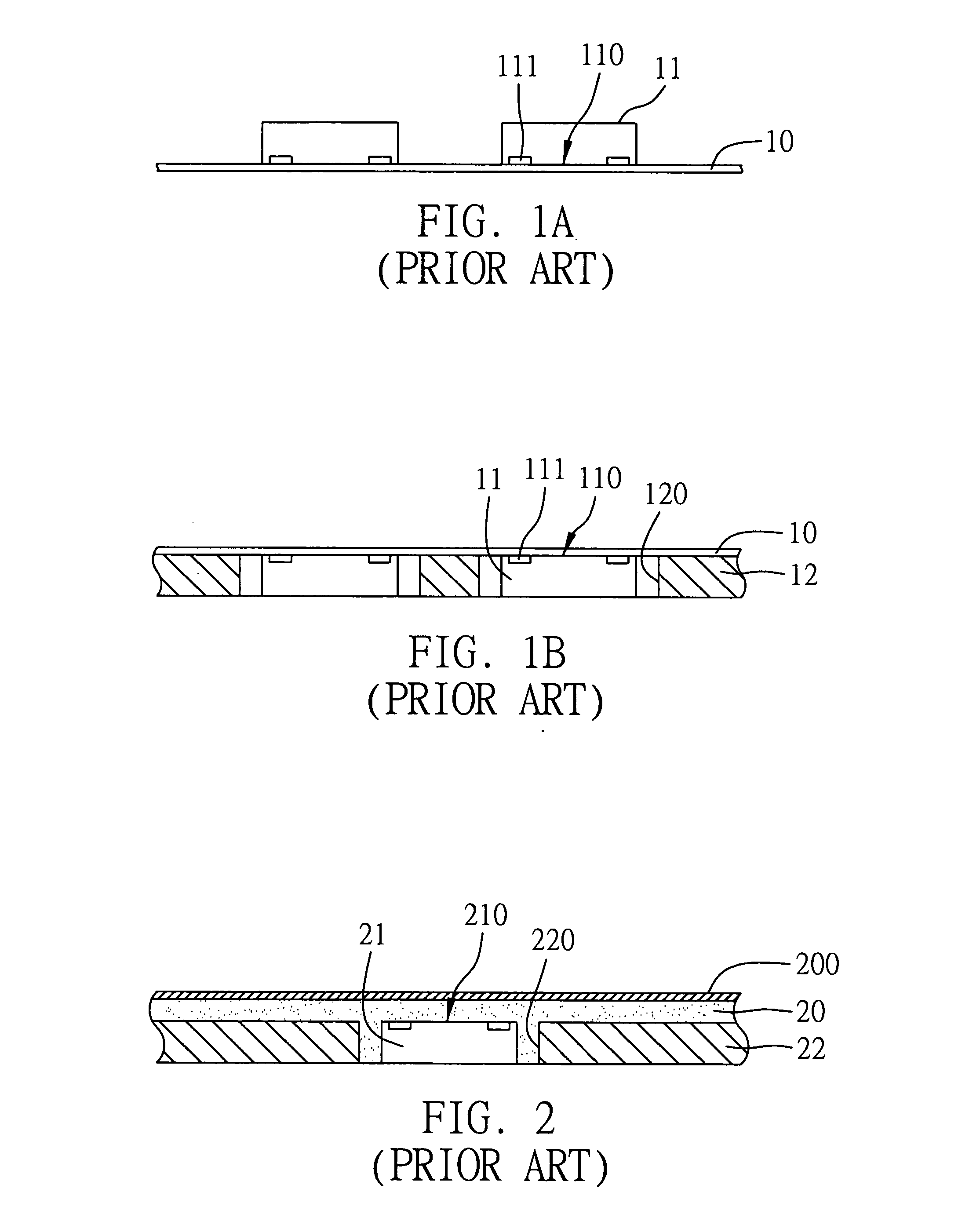
Although the requirement for a large number of I / O connections is met, during high-frequency usage or high-speed operation, the quality of electrical performance cannot be maintained due to the excessively long electrically conductive path in such BGA package.
Furthermore, the conventional packaging technology requires multiple connection interfaces, therefore increasing the fabrication cost thereof.
Furthermore, the use of the carrier film 10 not only increases the fabrication cost but also may generate and release organic substances during high-temperature fabrication processes to contaminate the chip 11 mounted thereon.
However, by the above method, the fabricated structure may have poor flatness due to the direct application of the resin 20 and makes it hard to be used in an advanced integrated circuit product.
Furthermore, the number of circuit layers needs to be increased to meet the requirements of advanced products, such that the fabrication cost is increased while the size miniaturization of the product is not facilitated as a consequence.

Method used


Image

  • Method of embedding semiconductor chip in support plate and embedded structure thereof
  • Method of embedding semiconductor chip in support plate and embedded structure thereof
  • Method of embedding semiconductor chip in support plate and embedded structure thereof

Examples


Embodiment Construction

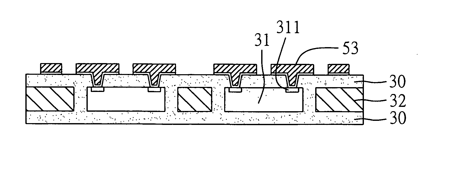
[0027] Preferred embodiments of a method of embedding a semiconductor chip in a support plate and an embedded structure thereof proposed in the present invention are described in detail as follows with reference to FIGS. 3 to 5. The drawings are made in simplicity and not based on actual dimensions, and only illustrate the components or parts relevant to the present invention.

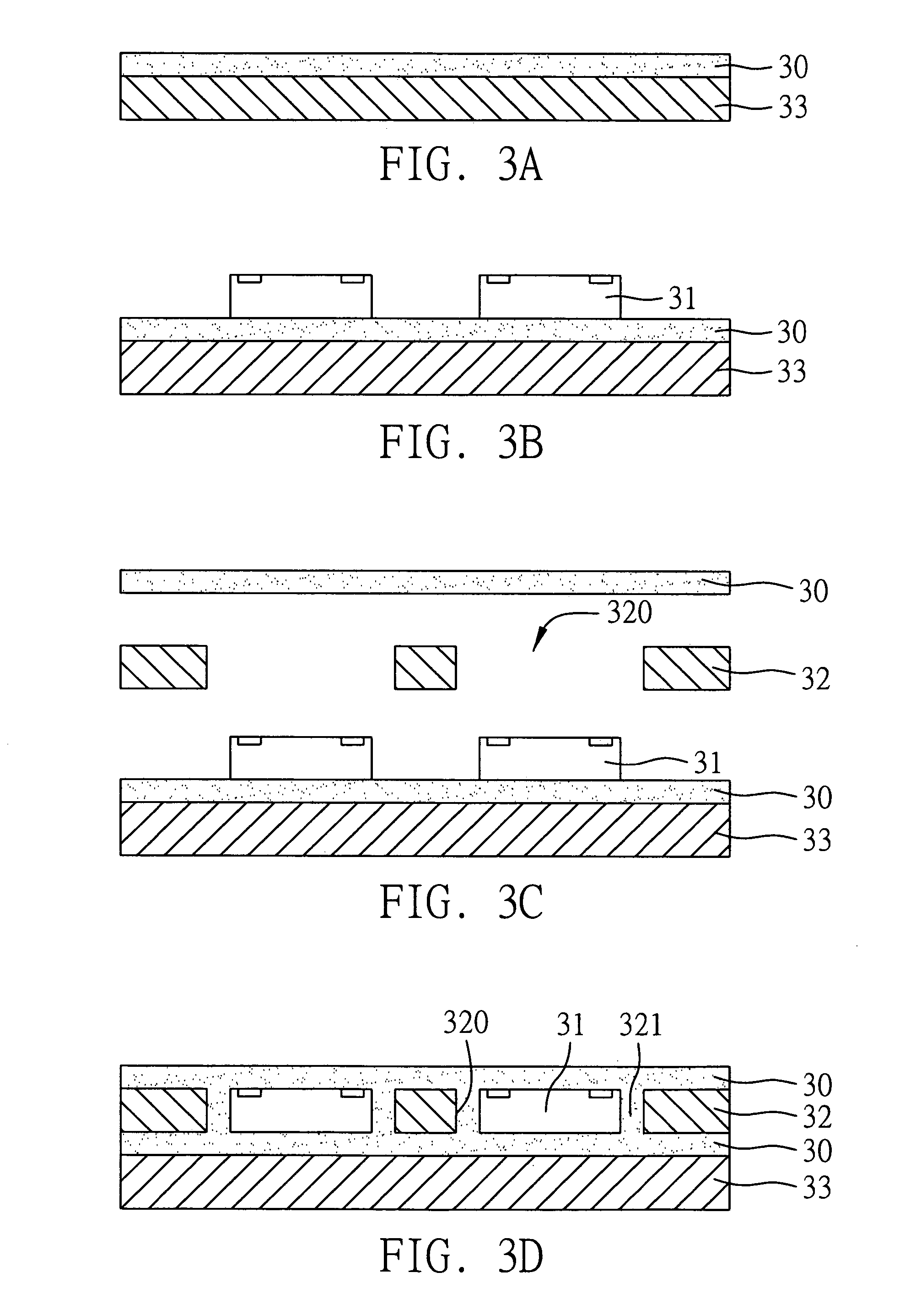
[0028]FIGS. 3A to 3D are cross-sectional views showing procedural steps of the method of embedding a semiconductor chip in a support plate according to a preferred embodiment of the present invention.

[0029] Referring to FIG. 3A, a dielectric layer 30 having a reinforced filling material is provided, wherein the reinforced filling material can be glass fiber. Then, a carrier plate 33 such as a metal plate can be attached to one side of the dielectric layer 30. Subsequently, referring to FIG. 3B, at least one semiconductor chip 31 is mounted on the dielectric layer 30 having the reinforced filling material, whe...


PUM


Abstract

A method of embedding a semiconductor chip in a support plate and an embedded structure thereof are proposed. A first dielectric layer having a reinforced filling material is provided, and a semiconductor chip is mounted on the first dielectric layer. A support plate having an opening and a second dielectric layer having a reinforced filling material are provided. The first dielectric layer mounted with the semiconductor chip, the support plate, and the second dielectric layer are pressed together, such that the semiconductor chip is received in the opening of the support plate, and the dielectric layers fill in a gap between the semiconductor chip and the opening of the support plate. The reinforced filling material of the dielectric layers can maintain flatness and consistency of the semiconductor chip embedded in the support plate, and fine circuits can be fabricated on the support plate by build-up and electroplating processes.

Description

FIELD OF THE INVENTION [0001] The present invention relates to methods of embedding semiconductor chips in support plates and embedded structures thereof, and more particularly, to a method of embedding an integrated circuit chip in an opening of a support plate, and an embedded structure thereof. BACKGROUND OF THE INVENTION [0002] Along with developments of the semiconductor packaging technology, there have been produced many different packaging types of semiconductor devices. In the semiconductor device, a semiconductor chip is mounted on a package substrate or lead frame, and then electrically connected to the package substrate or lead frame; subsequently, an encapsulant is fabricated to encapsulate the chip and form a package. Ball Grid Array (BGA) package involves an advanced type of the semiconductor packaging technology, which is characterized by the use of a package substrate whose front side is mounted with a semiconductor chip and whose back side is implanted with a grid a...

Claims


Application Information

Patent Timeline
IPC IPC(8): H01L23/28H01L21/44H01L21/56H01L23/31H01L23/48
CPCH01L21/56H01L2924/014H01L23/5389H01L24/19H01L24/20H01L24/24H01L24/82H01L25/50H01L2224/24227H01L2224/82039H01L2924/01029H01L2924/01082H01L2924/14H01L2924/01033H01L23/3107H01L2224/96H01L2224/04105H01L2924/3511
Inventor HSU, SHIH-PING
Owner PHOENIX PRECISION TECH CORP
Learn More