Film for optical elements

a technology of optical elements and films, applied in the field of films for optical elements, can solve the problems of reducing the display contrast, affecting the quality of the film, and the film cannot meet all of the above conditions, so as to improve the viewing angle and color compensation, improve the effect, and improve the viewing angl

Inactive Publication Date: 2001-09-25
NIPPON MITSUBISHI OIL CORP
View PDF7 Cites 16 Cited by
  • Summary
  • Abstract
  • Description
  • Claims
  • Application Information

AI Technical Summary

Benefits of technology

Where the transmission axes of upper and lower polarizing plates are orthogonal to each other, both polarizing plates are disposed so that the transmission axis of each polarizing plate and the rubbing direction of the liquid crystal cell closes to the polarizing plate are orthogonal or parallel to each other or at an angle of 45.degree.. Where a polarizing plate is disposed above the viewing angle improving film of the invention, the viewing angle improving effect will be obtained no matter in which of the above arrangements the polarizing plate may be. But it is most desirable to dispose upper and lower polarizing plates so that their transmission axes are orthogonal to each other. As to the relation between the transmission axis of a polarizing plate and the rubbing direction of the liquid crystal cell on the side closer to the polarizing plate, both parallel and perpendicular relations will do although there will be a slight difference in the viewing angle improving effect.
The viewing angle improving film of the present invention is greatly effective in improving the viewing angle of TN-LCDs using TFT or MIM elements and is also effective in improving the viewing angle and color compensation of other modes of LCDs such as STN (Super Twisted Nematic)-LCD, ECB (Electrically Controlled Birefringence)-LCD, OMI (Optical Mode Interference)-LCD, OCB (Optically Compensated Birefringence)-LCD, HAN (Hyrid Aligned Nematic)-LCD, and IPS (In Plane Switching)-LCD.
As described above, the film for optical elements according to the present invention fully satisfies reliability requirements such as high resistance to heat, to moisture and to light. Its strength is also high. Further, a wide range of conditions can be adopted for the orienting treatment, and the film, with little irregularity and few orientation defects, can be obtained industrially. Thus, its industrial application value is extremely high.

Problems solved by technology

However, the conventional TN-LCD inevitably involves a problem associated with a viewing angle such that there occurs change in display color or a lowering of display contrast when seen obliquely, due to refractive index anisotropy.
For this change it is required to establish appropriate manufacturing techniques and new manufacturing equipment, with consequent difficulty of manufacture and increase of cost.
However, in the case of forming a film with use of a known film material, it has been difficult for the film to fully satisfy all of the above conditions.

Method used


Image

  • Film for optical elements
  • Film for optical elements
  • Film for optical elements

Examples


reference example 1

Using 40 mmols of terephthalic acid, 40 mmols of 2,6-naphthalenedicarboxylic acid, 80 mmols of catechol diacetate, and 80 mmols of acetoxybenzoic acid, polymerization was carried out in a nitrogen atmosphere at 260.degree. C. for 4 hours, at 290.degree. C. for 2 hours, and then at 290.degree. C. for 4 hours in a current of nitrogen gas fed at a rate of 100 ml / min, to afford a liquid crystalline polyester (formula 1). This liquid crystalline polyester had an inherent viscosity of 0.16, had a nematic phase as a crystal phase, and had an isotropic phase--liquid crystal phase transition temperature of not lower than 300.degree. C. and a glass transition point of 120.degree. C.

Using this liquid crystalline polyester, there was prepared a 10 wt % solution thereof in a mixed phenol / tetrachloroethane solution (6 / 4 weight ratio) solvent. This solution was then applied onto a soda glass plate in accordance with a bar coating method, then dried, heat-treated at 190.degree. C. for 30 minutes, a...

reference example 2

Using 10 mmols of 4-octyloxybenzoic acid, 50 mmols of terephthalic acid, 45 mmols of naphthalenedicarboxylic acid, 50 mmols of catechol diacetate, 50 mmols of 3-methylcatechol diacetate, and 50 mmols of 4-acetoxybenzoic acid, a deacetylation polymerization was carried out in a nitrogen atmosphere at 270.degree. for 4 hours, and then at the same temperature for 2 hours in a current of nitrogen gas fed at a rate of 30 ml / min. The resulting reaction product was then dissolved in tetrachloroethane and thereafter purified by reprecipitation with methanol to afford a liquid crystalline polyester (formula 2). This liquid crystalline polyester had an inherent viscosity of 0.10, had a nematic phase as a liquid crystal phase, and had an isotropic phase-liquid crystal phase transition temperature of 240.degree. C. and a glass transition point of 75.degree. C.

Using the liquid crystalline polyester, there was prepared a 10 wt % solution thereof in a mixed phenol / tetrachloroethane (6 / 4 weight rat...

reference example 3

10 mmols of tert-butylhydroquinone diacetate and 20 mmols of 1,6-pentyloxy-2-naphthoic acid were reacted in a nitrogen atmosphere at 250.degree. C. for 4 hours, at 270.degree. C. for 2 hours, and then at 27.degree. C. for 2 hours in a current of nitrogen gas fed at a rate of 30 ml / min. Subsequent recrystallization of the resulting reaction product from a mixed methanol / ethyl acetate (1 / 1) solvent afforded the compound of formula (3).

Formula 3

##STR14##


PUM


Abstract

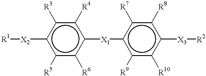
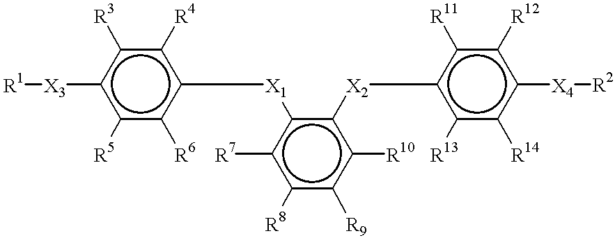
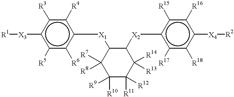
A film for optical elements is formed by a liquid crystalline composition comprising the following components (a) and (b):(a) a liquid crystalline polymer which exhibits an optically positive uniaxial property; and(b) a polycyclic compound having a molecular weight of not more than 1,000 and wherein a plurality of alicyclic rings and/or aromatic rings are connected together through a linkage chain of 0 to 4 main-chain carbon atoms bonded to different ring carbon atoms, with hydrocarbon groups each having 1 to 20 carbon atoms being bonded respectively to both end rings through a linkage chain of 0 to 4 main-chain carbon atoms,an orientation form formed in the state of liquid crystal of said liquid crystalline composition being fixed.

Description

The present invention relates to a film for optical elements in which the orientation of a composition containing a liquid crystalline polymer exhibiting a uniaxial property is fixed. More particularly, the invention is concerned with a viewing angle improving film and a twisted nematic liquid crystal display device having the said film.An active drive twisted nematic type liquid crystal display device (hereinafter referred to simply as "TN-LCD") using TFT element or MIM element affords an image quality comparable to a CRT as seen from the front side, in addition to the characteristics inherent in LCD such as small thickness, light weight and low power consumption. For this reason, the TN-LCD is spread widely as a display for notebook type personal computers, portable telephone and portable information terminals. However, the conventional TN-LCD inevitably involves a problem associated with a viewing angle such that there occurs change in display color or a lowering of display contr...

Claims


Application Information

Patent Timeline
Patent Type & Authority Patents(United States)
IPC IPC(8): G02B5/30G02F1/13C08J5/18C09K19/38G02B1/04G02F1/1335G02F1/13363
CPCG02B5/3016G02F1/133632Y10T428/1036Y10T428/10G02F2413/105C09K2323/00C09K2323/03
Inventor SATOH, YASUSHIMAZAKI, HITOSHIYAMANASHI, TERUAKIKOBORI, YOSHIHIRO
Owner NIPPON MITSUBISHI OIL CORP
Why Eureka
Try Eureka