Image display apparatus

a technology of image display and display device, which is applied in the direction of discharge tube/lamp details, magnetic discharge control, discharge tube luminescnet screen, etc., can solve the problems of reducing the amount of electrons emitted, adversely affecting the source, rendering it impossible to display bright images, etc., to reduce the brightness and color shift of images. even

Inactive Publication Date: 2006-03-09
CANON KK +1
View PDF12 Cites 13 Cited by
  • Summary
  • Abstract
  • Description
  • Claims
  • Application Information

AI Technical Summary

Benefits of technology

[0009] It is an object of the present invention to provide an image display apparatus in which uneven brightness and color shift of an image are reduced.

Problems solved by technology

If the pressure rises in the vacuum container interior due to gases being generated, while the extent of any adverse effects does depend on the type of gas, the electron source is adversely affected and the amount of electrons emitted is decreased, thus rendering it impossible for a bright image to be displayed.
For flat displays especially, gases generated from the image display member accumulate in the vicinity of the electron source before reaching a getter arranged outside of the image display area, thus causing problems characterized by localized pressure rise and the resulting electron source deterioration.
However, while the exhaust velocity of water or oxygen by an evaporating type getter is extremely large, the exhaust velocity of an inert gas such as argon (Ar) by either an evaporating type getter or a non-evaporating type getter is almost zero.
In some cases this can cause internal electric discharge, whereby the apparatus can be destroyed.
However, magnetic field leaking from the magnetic field generating means 920 acts on the electron beam whose purpose is to display the image, whereby the beam orbit is changed, thereby causing the beam to deviate when arriving at the phosphor from the location where the beam originally would have arrived.
Therefore, there are the problems of members other than the phosphor being bombarded, brightness being reduced due to the beam arriving at an adjacent portion of the phosphor, and color shift occurring in a color image.

Method used


Image

  • Image display apparatus
  • Image display apparatus
  • Image display apparatus

Examples


example 1

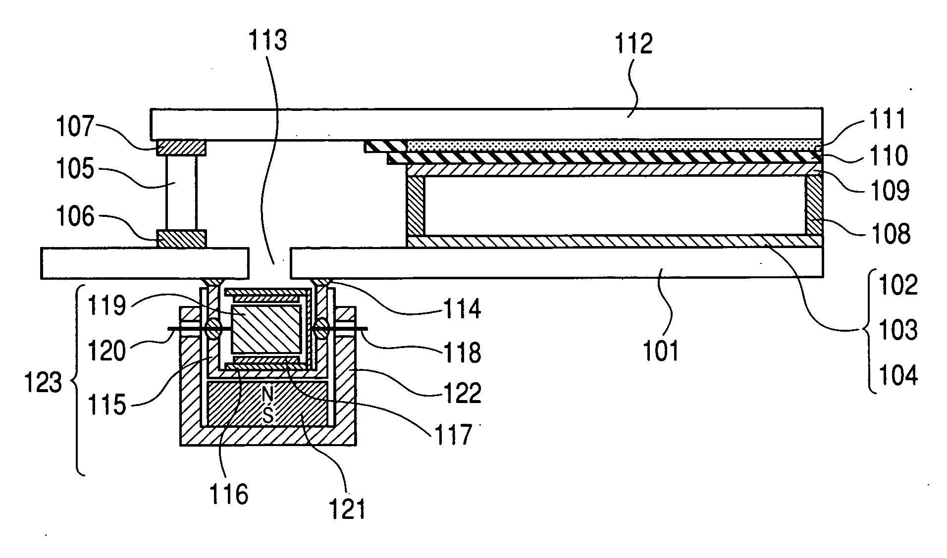
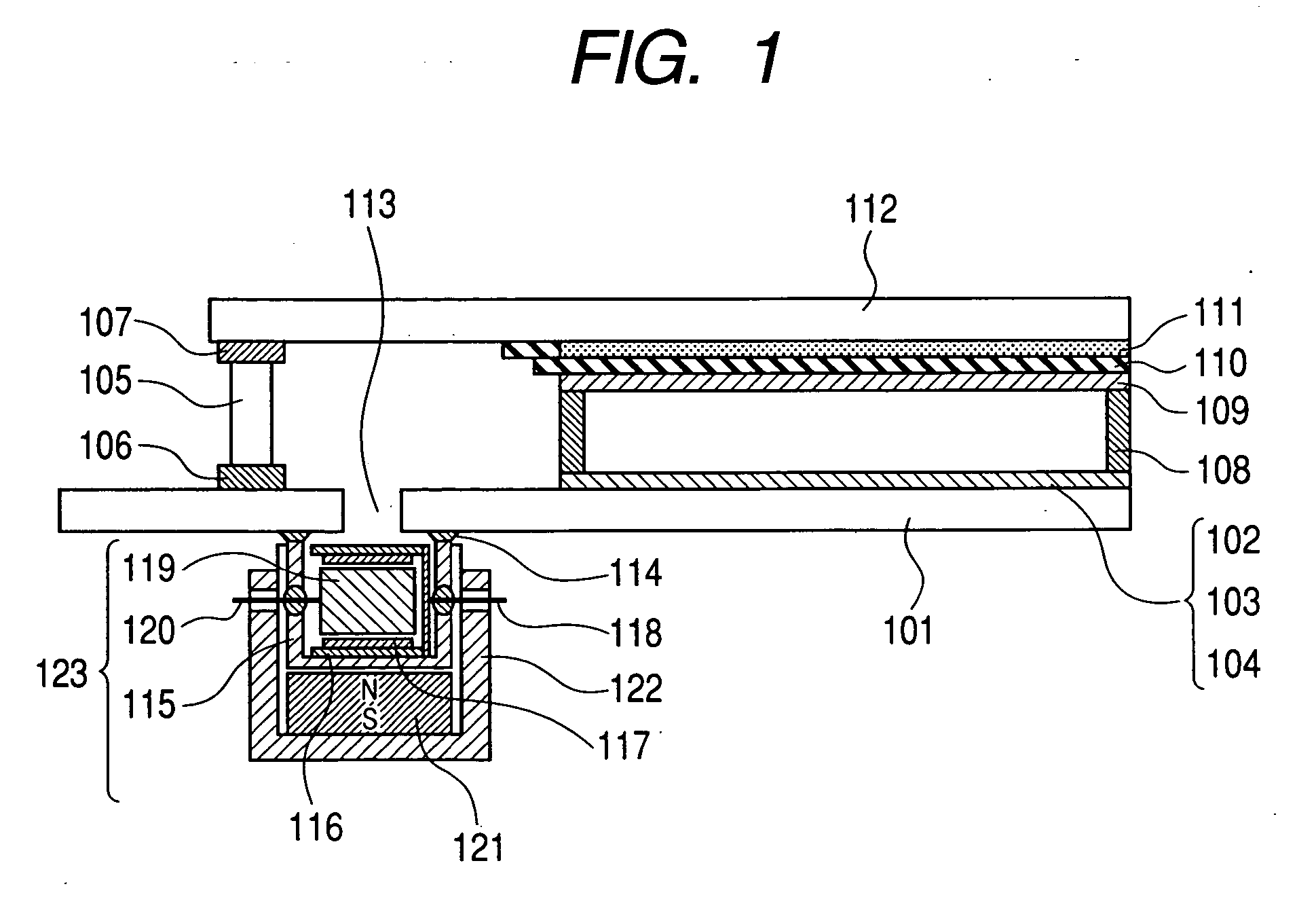
[0060] This example shall be explained with reference to the image display apparatus illustrated in FIG. 1.

[0061] First, the method for producing the package which serves as a vacuum container for the image display apparatus will be explained. Using glass plates (PD-200, manufactured by Asahi Glass Co., Ltd.) having a thickness of 2.8 mm and a size of 240 mm×320 mm as the rear plate 101, and having a thickness of 2.8 mm and a size of 190 mm×270 mm as the face plate 112, a layer of SiO2 (not shown) 500 nm thick was deposited on the electron source side surface of the rear plate 101, and an ITO film (not shown) was deposited to a thickness of 50 nm on the underside. An exhaust port 113 having an 8 mm φ (diameter) was provided outside of the image region and inside of the glass frame 105.

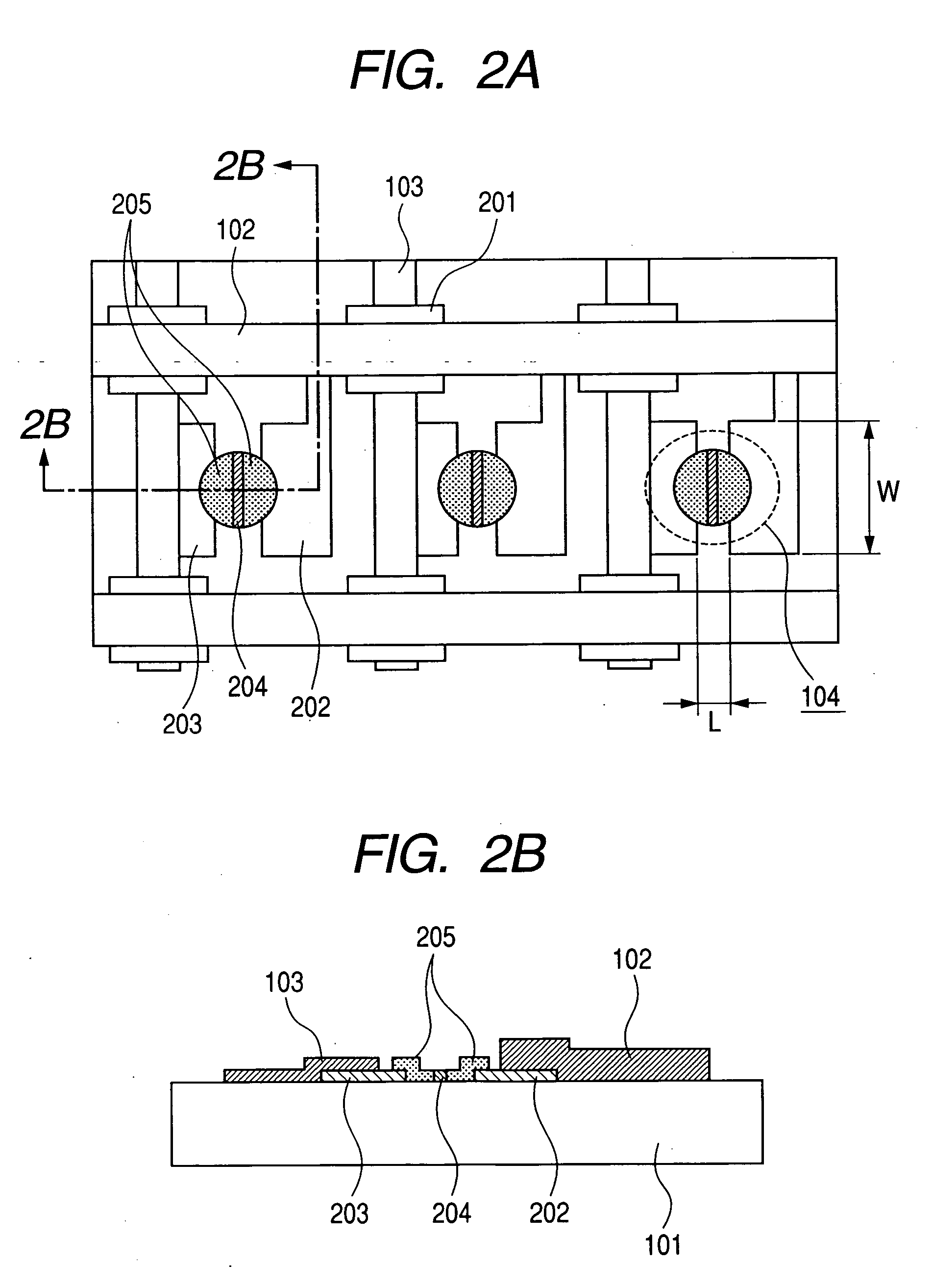
[0062] The device electrodes 202 and 203 of the surface conducting electron-emitting devices 104 serving as an electron source were produced by depositing platinum onto the above-described rear plate...

example 2

[0079] In this Example, as illustrated in FIG. 6, an example wherein the ion pump 123 is arranged on a face plate 612 will be explained. As illustrated in FIG. 6, the exhaust port 613 is open to the face plate 112. Other than that, the members having reference numerals the same as those for members which have been illustrated in the preceding figures represent the same members. First, the method for producing a package which serves as the vacuum container of the image display apparatus will be described.

[0080] Except for not having an exhaust port, the rear plate 601 was the same as that in Example 1. Next, in the same manner as in Example 1, surface conducting electron-emitting devices 104, upper wiring 102 and lower wiring 103 were formed on the rear plate 601, and a support frame 105 the same as in Example 1 was seal-bonded thereto. Forming and activation were carried out in the same manner as in Example 1. Indium was subsequently coated onto the support frame 105, and spacers 1...

example 3

[0085] In this Example, as illustrated in FIG. 7, an example wherein a field emission type electron-emitting device 700 is used as the electron source will be explained. As illustrated in FIG. 7, on a insulating layer 704 which was above a rear plate 701 are formed a negative electrode 702, a positive electrode 703, and an electron-emitting member 705 for emitting electrons at a tip thereof made into an acute angle, to thereby constitute a field emission type electron-emitting device 700. In such a constitution, if voltage is applied to the negative electrode 702 and the positive electrode 703 so that the positive electrode 703 has a higher potential, the electric field concentrates at the electron-emitting member 705, whereby electrons are emitted from the electron-emitting member 705 due to the tunnel effect.

[0086] The method for producing the image display apparatus according to the present example will now be explained. Using the same substrate as that in Example 1 for the rear...


PUM


Abstract

It is an object of the present invention to provide an image display apparatus in which the change over time of its electron source characteristics is small, and in which uneven brightness and color shift of an image is almost unnoticeable. To achieve this object, the present invention is directed to an image display apparatus containing an electron source substrate having a plurality of electron-emitting devices arrayed thereon, an image forming substrate arranged so as to face the electron source substrate and having a phosphor film and an anode electrode film, and magnetic field generating means, wherein a component parallel to the electron source substrate of a magnetic flux density of a magnetic field generated by the magnetic field generating means is not greater than 0.01 Tesla at any location of the electron-emitting devices.

Description

BACKGROUND OF THE INVENTION [0001] 1. Field of the Invention [0002] The present invention relates to an image display apparatus employing an electron-emitting device. [0003] 2. Related Background Art [0004] In a flat display in which a plurality of electron-emitting devices are arrayed on a flat substrate as an electron source, and an electron beam emitted from the electron source is irradiated at a phosphor which serves as an image forming member on an opposing substrate, whereby an image is displayed by light emitted from the phosphor, it is necessary to maintain to a high vacuum the interior of the vacuum container which encapsulates the electron beam and the image forming member. If the pressure rises in the vacuum container interior due to gases being generated, while the extent of any adverse effects does depend on the type of gas, the electron source is adversely affected and the amount of electrons emitted is decreased, thus rendering it impossible for a bright image to be d...

Claims


Application Information

Patent Timeline
Patent Type & Authority Applications(United States)
IPC IPC(8): H01J1/50H01J23/10H01J29/76H01J3/32
CPCH01J29/845H01J2329/00H01J29/94
Inventor SATO, YASUEKAMIO, MASARUGOFUKU, IHACHIROTSUDA, HISANORINARUSAWA, TOMOKOSHIMADA, YOSHIYUKIMITANI, HIROMASASEINO, KAZUYUKINISHIMURA, TAKASHI
Owner CANON KK
Why Eureka
Try Eureka