Output voltage ripple reduction technique for burst mode operation of power converter

a technology of power converter and output voltage ripple, which is applied in the direction of electric variable regulation, process and machine control, instruments, etc., can solve the problem that the output voltage ripple can be many times larger than during normal operation, and achieve the effect of reducing power consumption and minimizing the amount of energy transferred

Inactive Publication Date: 2006-03-09
SYNQOR
View PDF1 Cites 18 Cited by
  • Summary
  • Abstract
  • Description
  • Claims
  • Application Information

AI Technical Summary

Benefits of technology

[0004] The addition of auxiliary circuitry can overcome defects and undesirable operation of power control ICs. Some control chips employ a burst-mode, or discontinuous conduction mode, to reduce power consumption at light load conditions. Ideally, the power switching devices are driven for a minimal duration “burst” and then held off for a period of time until the controller detects that the output voltage is beginning to sag. This minimal duration is preferably a single switching cycle, perhaps using the minimum duty cycle, or otherwise minimizing the amount of energy transferred to the output. If the control method or noise sensitivity causes the converter to operate for multiple cycles during each burst, the output voltage ripple can be many times larger than during normal operation.

Problems solved by technology

If the control method or noise sensitivity causes the converter to operate for multiple cycles during each burst, the output voltage ripple can be many times larger than during normal operation.

Method used


Image

  • Output voltage ripple reduction technique for burst mode operation of power converter
  • Output voltage ripple reduction technique for burst mode operation of power converter
  • Output voltage ripple reduction technique for burst mode operation of power converter

Examples


Embodiment Construction

[0013] A detailed description of preferred embodiments of the invention follows.

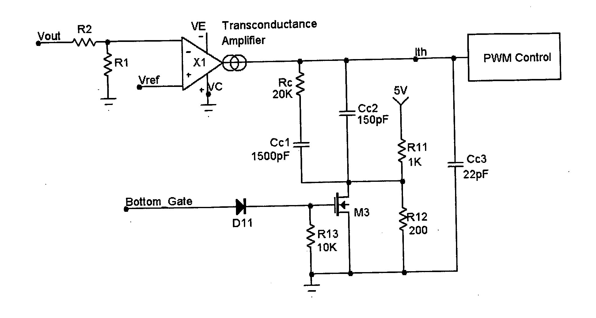
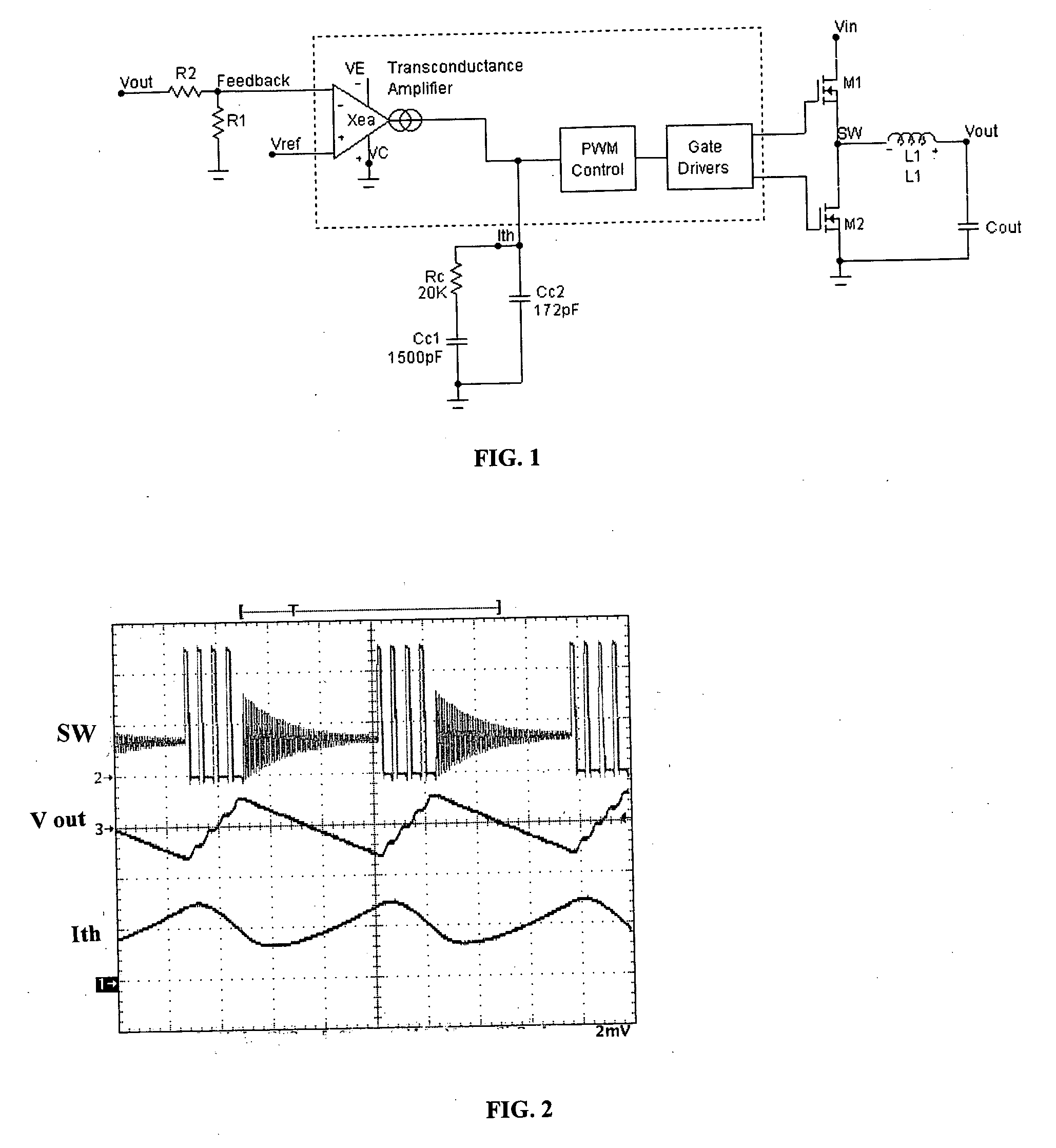
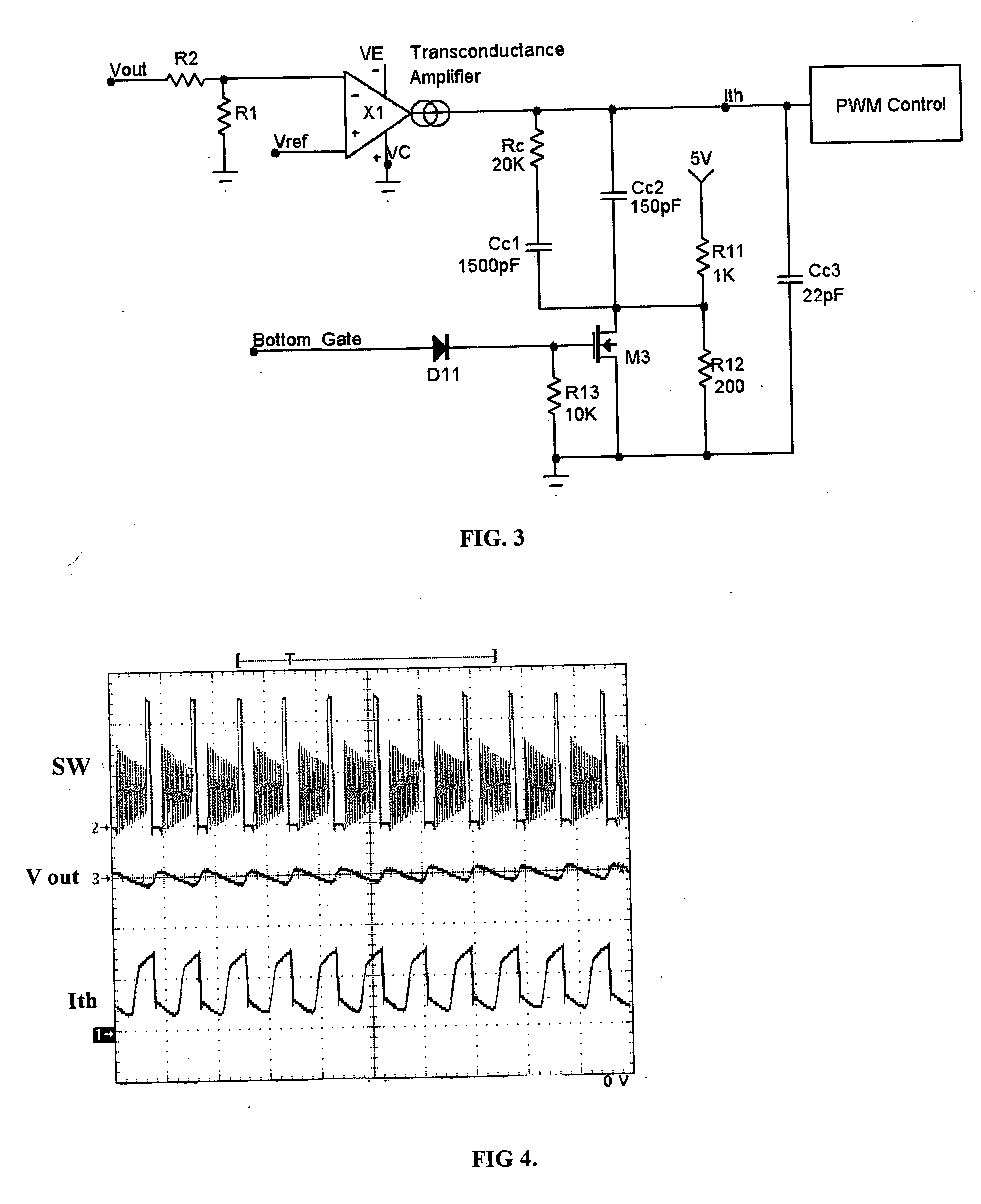
[0014]FIG. 1 illustrates a conventional buck converter circuit based on a control chip such as the LTC3770 chip provided by Linear Technology of San Jose, Calif. The MOSFET transistors M1 and M2 are alternately switched to connect an input node SW to a high voltage VIN and a low voltage ground. The input is to a reactive circuit including an inductor L1 and capacitor Cout. The gates of transistors M1 and M2 are driven by a controller IC such as an LTC3770 controller or an LTC3778 controller. The control chip, shown in broken lines, includes a PWM controller and gate drivers for the MOSFETs M1 and M2. The controller operates continuously at a varying frequency depending on the load conditions or, at light loads, operates in a burst mode. A control element within the chip, utilized with the present invention, is the XEA transconductance error amplifier.

[0015]FIG. 1 shows a simplified block diagram of a s...


PUM


Abstract

A power converter is controlled by a control circuit that includes a burst mode operation during low load conditions. A compensation circuit modifies a control signal to reduce the number of switch cycles during a burst. The compensation circuit includes a time-variant offset to the control signal that is removed when the power converter input signal is connected to low voltage.

Description

RELATED APPLICATION [0001] This application claims the benefit of U.S. Provisional Application No. 60 / 604,866, filed on Aug. 27, 2004. The entire teachings of the above application are incorporated herein by reference.BACKGROUND [0002] DC / DC power converters are often built using integrated control chips. These control chips direct the operation of other parts of the power converter, implementing some of the control features required to create a well-behaved circuit. However, many of the existing control chips do not always function properly, so that power converters built with these controllers do not behave as desired under certain conditions. [0003] One type of control feature often implemented by control ICs is a means to reduce power consumption at light load conditions. These control means often employ burst-mode or discontinuous conduction mode operation. In general, this type of feature tends to increase the AC voltage ripple on the output of the power converter. Depending o...

Claims


Application Information

Patent Timeline
Patent Type & Authority Applications(United States)
IPC IPC(8): G05F1/56
CPCH02M3/158Y02B70/16H02M2001/0032Y02B70/10H02M1/0032
Inventor FARKAS, THOMAS
Owner SYNQOR
Why Eureka
Try Eureka