Integrated wavefront correction module

a wavefront correction and integrated technology, applied in the direction of mirrors, instruments, mountings, etc., can solve the problems of reducing the tilt motion, and increasing the cost. , to achieve the effect of amplifying the tilt motion

Inactive Publication Date: 2006-03-09
XINETICS
View PDF6 Cites 10 Cited by
  • Summary
  • Abstract
  • Description
  • Claims
  • Application Information

AI Technical Summary

Benefits of technology

[0005] It is a further object of this invention to provide such an integrated wavefront correction module, which is smaller, simpler and less expensive.
[0006] The invention results from the realization that a truly improved smaller, more compact and less expensive wavefront correction module can be achieved by integrating the tip-tilt correction function and high spatial and temporal frequency wavefront correction function in a single device in which a deformable mirror that corrects for the high spatial and temporal frequency wavefront errors is carried by a tip-tilt mechanism which corrects for the tip-tilt error.

Problems solved by technology

Having two correction devices requires additional optical relays to be incorporated in the system, which in turn translates into more cost, size and complexity.

Method used


Image

  • Integrated wavefront correction module
  • Integrated wavefront correction module
  • Integrated wavefront correction module

Examples


Embodiment Construction

[0034] Aside from the preferred embodiment or embodiments disclosed below, this invention is capable of other embodiments and of being practiced or being carried out in various ways. Thus, it is to be understood that the invention is not limited in its application to the details of construction and the arrangements of components set forth in the following description or illustrated in the drawings.

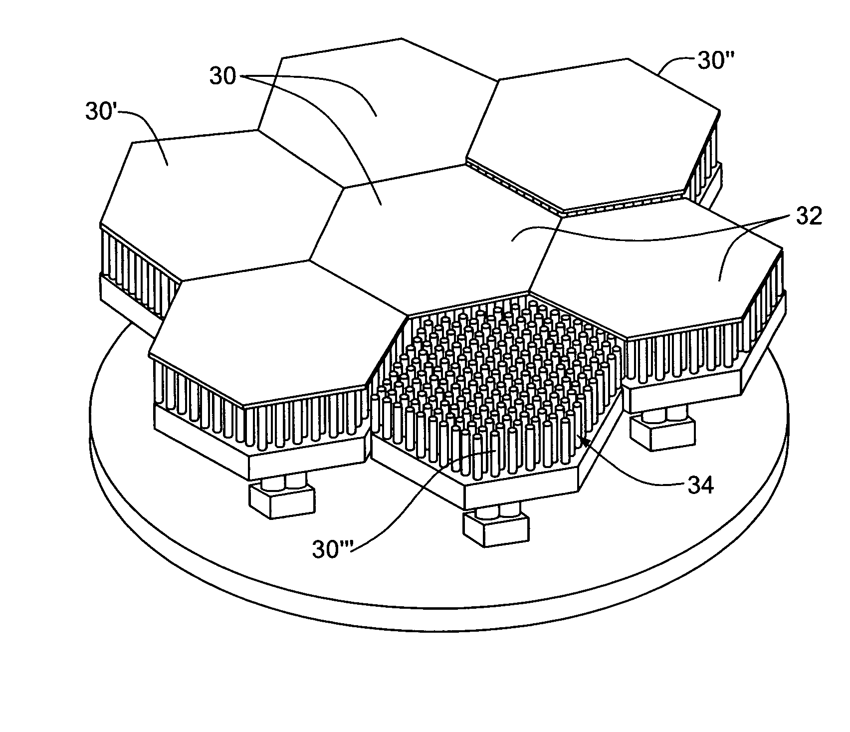
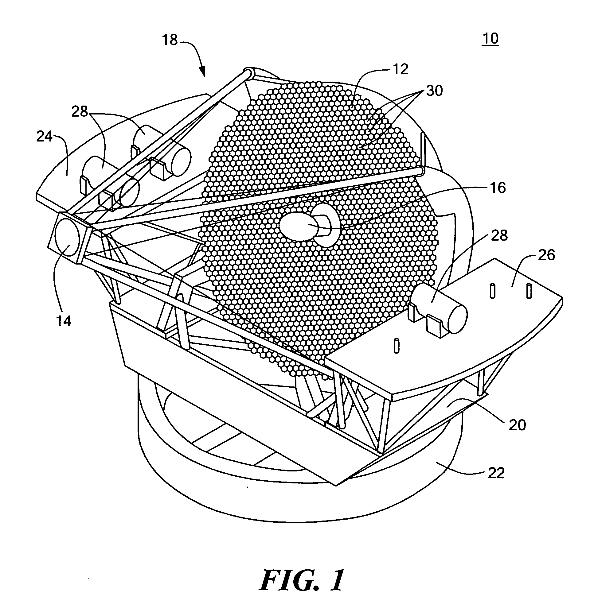
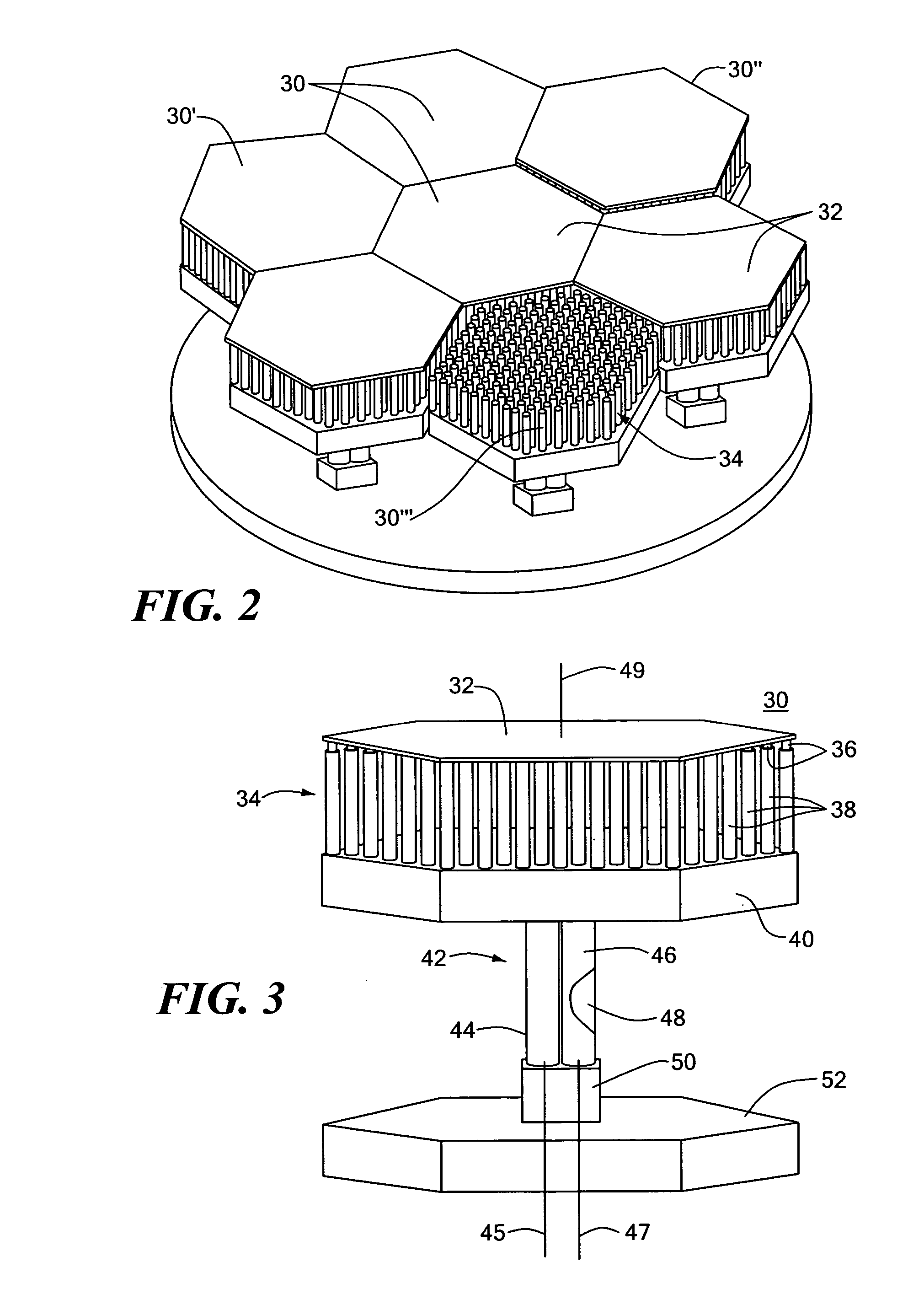
[0035] There is shown in FIG. 1 an adaptive telescope system 10 including a primary segmented mirror 12, secondary segmented mirror 14, and tertiary segmented mirror 16 all of which are mounted by means of the superstructure 18 on yolk 20 carried by pier 22. Instrument platforms 24, 26 carry instrumentation, controls and sensing equipment and circuits. Each of the mirrors, primary 12, secondary 14, and tertiary 16 are made up of phased segments implemented by the integrated wavefront correction modules 30 according to this invention a number of which are shown in FIG. 2 as having a hexago...


PUM


Abstract

An integrated wave front correction module includes an optical surface; a high spatial and temporal frequency correction system for deforming the optical surface to correct for high spatial and temporal frequency phase errors in an incident wavefront on the optical surface; and a tip-tilt correction system for adjusting the optical surface to compensate for tip-tilt errors in the incident wavefront.

Description

FIELD OF THE INVENTION [0001] This invention relates to an integrated wavefront correction module. BACKGROUND OF THE INVENTION [0002] Typical adaptive optics systems require a deformable mirror to provide high spatial and temporal frequency wavefront correction and a separate tip-tilt mirror so that the deformable mirror's dynamic range is not exhausted on low order aberrations. Having two correction devices requires additional optical relays to be incorporated in the system, which in turn translates into more cost, size and complexity. BRIEF SUMMARY OF THE INVENTION [0003] It is therefore an object of this invention to provide an integrated wavefront correction module. [0004] It is a further object of this invention to provide such an integrated wavefront correction module which effects both high spatial and temporal frequency and tip-tilt correction in a single device. [0005] It is a further object of this invention to provide such an integrated wavefront correction module, which ...

Claims


Application Information

Patent Timeline
Patent Type & Authority Applications(United States)
IPC IPC(8): G01J1/20
CPCG02B26/0825G02B26/06
Inventor EALEY, MARK A.
Owner XINETICS
Why Eureka
Try Eureka