
High-power sono-chemical reactor

a high-power, sono-chemical technology, applied in shaking/oscillation/vibration mixers, mixers, mechanical vibration separation, etc., can solve the problems of reducing the efficiency of ultrasound energy attenuation

Inactive Publication Date: 2006-03-09
NANO EM
View PDF8 Cites 7 Cited by
  • Summary
  • Abstract
  • Description
  • Claims
  • Application Information

AI Technical Summary

Benefits of technology

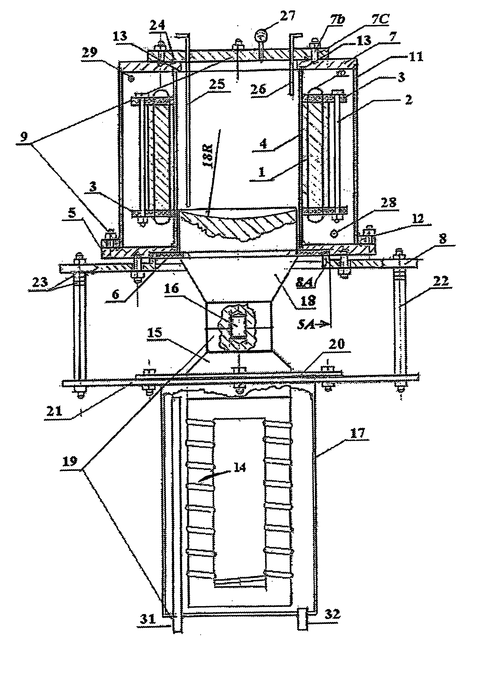
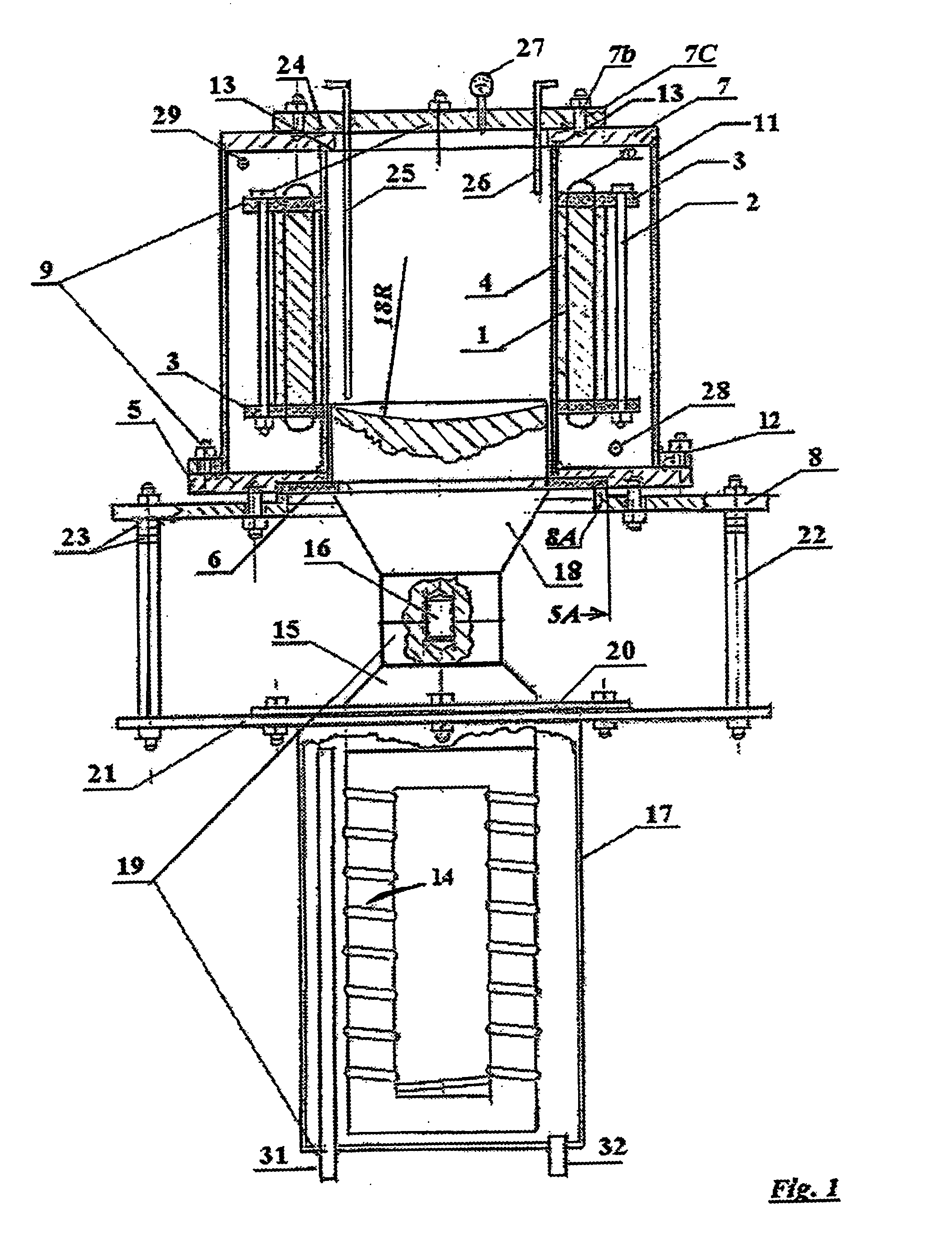
[0032] According to still further features in the described preferred embodiments, the device further includes a flexible pad or gasket, disposed between the first and second magnetostrictors, for hermetically sealing between the wave guide and the reaction volume, and for enabling acoustical communication between the first and second magnetostrictors.
[0043] According to still further features in the described preferred embodiments, the activating of the magnetostrictors is performed to effect, within the reaction volume, a specific energy of 1.4-4.2 W / cm3, so as to efficiently produce the nano-emulsion.

Problems solved by technology

This construction has an adverse effect of attenuating useful transmissions of high-intensity ultrasound energy.
Moreover, the piezo-ceramic generators transmit low-energy ultrasound through the walls of the reactor, causing a considerable energy loss.
Furthermore, the cavitation bubbles generated on the walls of the reactor cause an additional loss in ultrasound energy, as the gas bubbles absorb the ultrasound.
Because of these shortcomings, the efficiency of the above reactors is considerably low, never achieving more than 25-30%.
Because of the low useful energy generated by the ultrasound reactors of the prior art (e.g., the reactor disclosed in WO 97 / 02088 PCT), the emulsion production rates of such reactors are correspondingly low.
This arrangement, however, precludes the process from achieving high production rates, because most of the useful energy is absorbed by the considerable mass of the ring.
Furthermore, the remaining useful energy is diminished by a sonotrode construction having poor acoustic properties.
The shortcomings of the construction are further exacerbated by the high-amplitude oscillations, which cause material fatigue of the rings.
Additionally, since the diameter of a ring is dictated by the wavelength of the ultrasound, it becomes technically impossible for a transducer having a power rating of 200-400 kW (the power rating cannot exceed 1 kW due to the accelerated fatigue of the construction materials) to be connected to a ring whose diameter is about 30 mm for operating at a frequency of 20 kHz.
This narrow diameter further limits raw material flowrate, and, consequently, productivity.
The above reactor, however, is complicated and expensive to build, demanding that transducers are strictly synchronized in phase.
Moreover, the relatively small size of the concentrated energy region does not allow for emulsification or homogenization of materials in a continuous mode on an industrial scale.
The design utilizes standard sonotrodes, from which it follows that the design suffers from low production efficiency and from a high rate of erosion of the waveguides.
Tests performed by the inventor show that this homogenizer fails to produce emulsions having a sufficiently low droplet size.
Moreover, the design requires an unusually large reactor, because the twelve low-efficiency sonotrodes discharge a copious quantity of heat, thereby creating the need for an extremely large cooling system.
It is evident from all of the above that the above-described prior art is fundamentally incapable of providing the high specific-energy required for industrial production of nano-emulsions, due, inter alia, to poor sonotrode efficiency.
The reactors disclosed by the prior art also require frequent maintenance of the ultrasound-generating equipment due to rapid erosion thereof.
The disparity of the longitudinal and the transversal dimensions of the reactor causes the ultrasonic energy to be distributed in a non-homogenous pattern, thereby decreasing the volume available for useful cavitation, and ultimately leading to a low product throughput.

Method used


Image

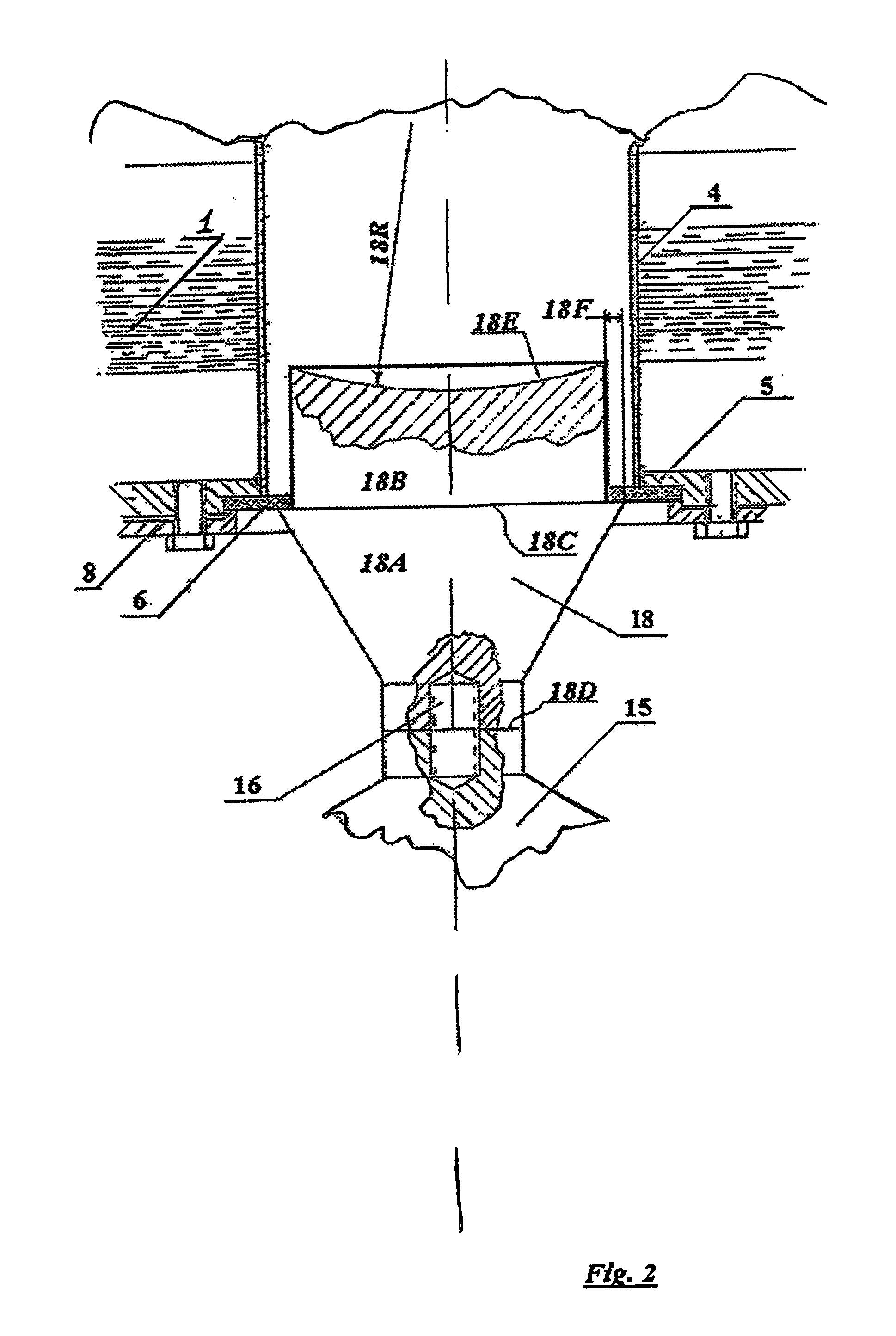
  • High-power sono-chemical reactor
  • High-power sono-chemical reactor
  • High-power sono-chemical reactor

Examples


Embodiment Construction

[0055] The principles and operation of the reactor according to the present invention may be better understood with reference to the drawings and the accompanying description.

[0056] Before explaining at least one embodiment of the invention in detail, it is to be understood that the invention is not limited in its application to the details of construction and the arrangement of the components set forth in the following description or illustrated in the drawing. The invention is capable of other embodiments or of being practiced or carried out in various ways. Also, it is to be understood that the phraseology and terminology employed herein is for the purpose of description and should not be regarded as limiting.

[0057] As used herein in the specification and in the claims section that follows, the term “transducer” refers to a device that converts input electromagnetic or electrical energy into output energy in the form of ultrasound.

[0058] As used herein in the specification and...


PUM

PropertyMeasurementUnit
Diameteraaaaaaaaaa
Frequencyaaaaaaaaaa
Frequencyaaaaaaaaaa

Abstract

A device and method for sono-chemical processing, including a reactor bounded by a substantially cylindrical wall, the reactor having: a reaction volume, defined by the wall; first and second magnetostrictors, associated with the reaction volume, the wall and the magnetostrictors designed and disposed such that the first magnetostrictor produces a first series of ultrasonic waves having a first frequency within the reaction volume, the second magnetostrictor produces a second series of ultrasonic waves having a second frequency within the reaction volume, wherein the second frequency exceeds the first frequency.

Description

[0001] This application draws priority from U.S. Provisional Patent Application Ser. No. 60 / 607,591, filed 8 Sep., 2004.FIELD AND BACKGROUND OF THE INVENTION [0002] The present invention relates to a method and device for effecting and enhancing chemical reactions and processes, and more particularly, to a method and device for producing water-and-hydrocarbon nano-emulsions. [0003] Emulsions containing water and diesel oil have drawn much interest as being ecologically clean fuels. [0004] The emulsification of two such immiscible liquids involves thermodynamically treating the liquids so as to destroy the cohesive forces within a liquid, so as to form extremely small droplets. [0005] The most efficient method to produce nano-emulsions involves achieving cavitation within the liquids to be emulsified. Cavitation is a well-known effect wherein, due to disruption of cohesive forces by an external mechanical action upon a liquid, bubbles are formed, which are immediately filled with gas...

Claims


Application Information

Patent Timeline
IPC IPC(8): B01F11/00
CPCB01F3/0819B01F11/0258B01F2003/0834B01F2003/0842B06B3/00B01J19/10B01J2219/00085B01J2219/00243B01J2219/0888B01F2215/0454B01F23/4111B01F23/4143B01F23/4145B01F31/85
Inventor MARKHASIN, EVGENY
Owner NANO EM
Learn More