Coolant recirculation equipment for nuclear reactor

a technology of reactors and equipment, applied in nuclear engineering, nuclear elements, greenhouse gas reduction, etc., can solve the problems of large and complicated changes in the layout or design of reactor pressure vessels, equipment or devices disposed therein, and the maintenance and/or inspection of internal pumps, so as to reduce the number of internal pumps and improve the workability of wor, the effect of reducing the flow rate of core coolan

Inactive Publication Date: 2006-03-09
KK TOSHIBA
View PDF14 Cites 2 Cited by
  • Summary
  • Abstract
  • Description
  • Claims
  • Application Information

AI Technical Summary

Benefits of technology

[0021] The present invention was conceived in consideration of the circumstances in the prior art mentioned above and an object of the present invention is to provide a reactor coolant recirculation equipment, in which a cooling water system of internal pumps can be simplified to thereby improve workability of workers or operators in a lower drywell in a reactor pressure vessel of a nuclear power plant, and, moreover, it makes possible to reduce the number of the internal pumps to be arranged without reducing the core coolant flow rate even in a case of fault of a power-supply section in comparison with a conventional arrangement of a nuclear power plant.
[0034] According to the present invention of the characters mentioned above, the ten positions are set as internal pump installation positions at substantially same interval in a circumferential direction around a central portion of the bottom portion of the reactor pressure vessel, and nine or less and four or more numbers of the internal pumps are installed at the ten internal pump installation positions. Thus, the reduction of the numbers of the internal pumps to be installed can be achieved, thus being advantageous.
[0035] Furthermore, a plurality of internal pumps are connected to one heat exchanger, which has the inner portion divided into a plurality of sections corresponding to the numbers of the internal pumps connected thereto as the cooling water passing sections. According to such structure, the cooling water supply system for the internal pumps can be simplified and workability and accessibility of the worker in the lower drywell can be improved. Still furthermore, even at a time of power-supply fault, the core coolant flow amount can be still maintained properly in comparison with the conventional structure of the nuclear reactor plant.

Problems solved by technology

Accordingly, a moving working of a worker inside the lower drywell 6 may interfere with the internal pump maintenance and / or inspection working.
However, as mentioned before, in a usual conventional design, since the ten internal pumps 3 are arranged, the reduction of the installation number of the internal pumps resulted in considerable and complicated change of layout or design of the reactor pressure vessel or equipments or devices disposed therein.
However, in the case that cooling water pipes or like of a plurality of internal pumps 3 are combined, it becomes difficult to maintain a stable cooling performance or ability properly responding to the operating condition of the respective internal pumps 3.
For example, in a case where the cooling water pipes of the plural internal pumps 3 are combined under a condition that one side internal pump is tripped or the internal pumps are operated at different revolution numbers, there may cause a case that, because of the difference of powers of the respective pumps, the cooling water does not circulate on the one side internal pump and it is hence difficult to maintain the temperature around the motor section below a predetermined allowable temperature.
Furthermore, in a case where two adjacent internal pumps are cooled by one heat exchanger in the arrangement mentioned above, there is a fear that if the power-supply system in one section becomes faulty or disordered, seven or more internal pumps 3 may become inoperative.

Method used


Image

  • Coolant recirculation equipment for nuclear reactor
  • Coolant recirculation equipment for nuclear reactor
  • Coolant recirculation equipment for nuclear reactor

Examples


first embodiment

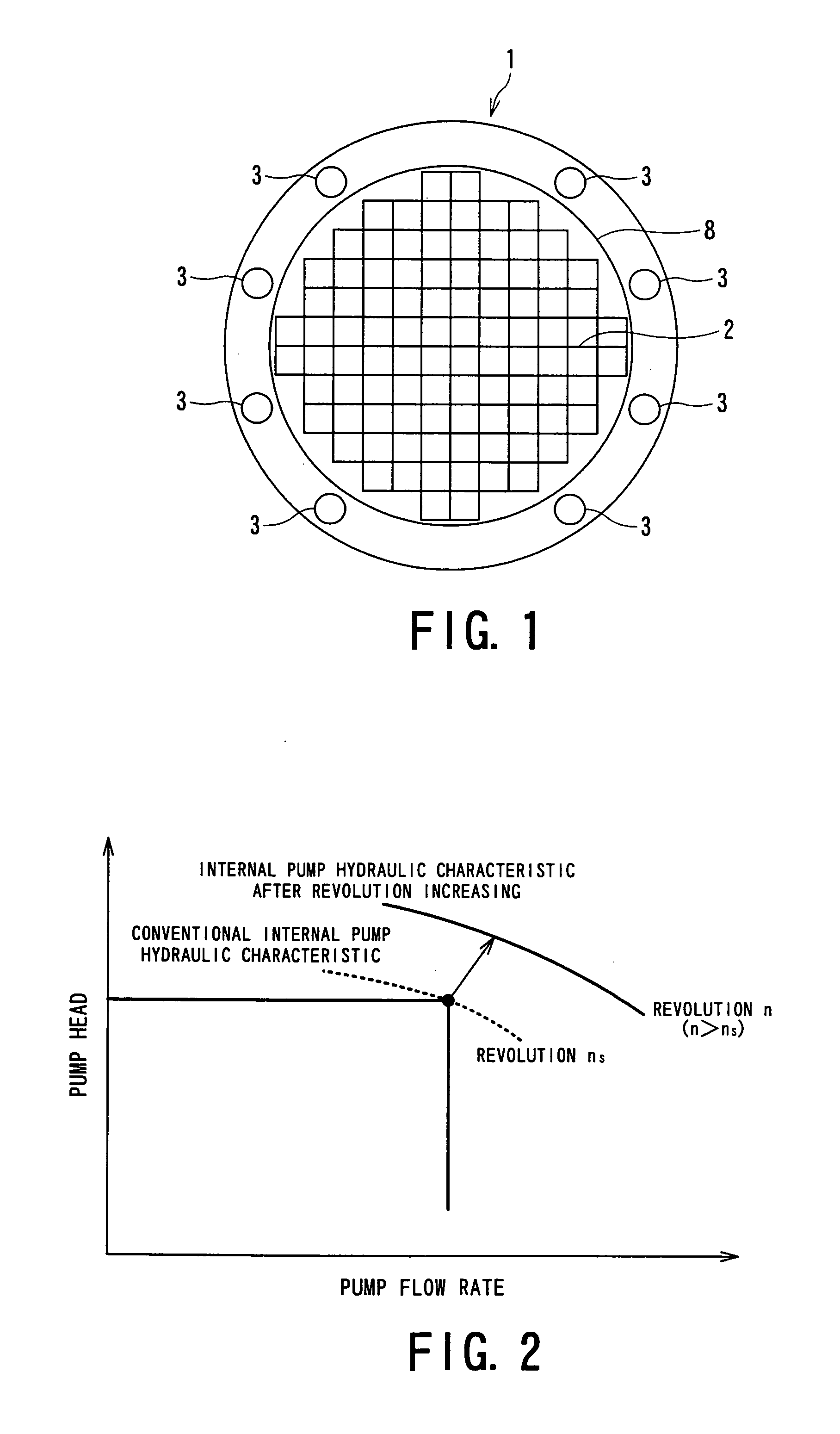
[0051] A first embodiment of a nuclear reactor coolant recirculation equipment or system of the present invention will be first described with reference to FIGS. 1 and 2.

[0052] With reference to FIG. 1, a plurality of internal pumps 3 are arranged at a peripheral portion of a bottom portion of a reactor pressure vessel 1 of a boiling water type light water reactor, which may be called herein as boiling-light-water reactor. In this reactor coolant recirculation equipment, the internal pumps 3 are driven by electric motors each provided for each internal pump 3, and the internal pumps 3 are also provided with power-supply units or sections for driving the motors, cooling water pipes for cooling the internal pumps 3, heat exchangers for the internal pumps, and auxiliary cooling water pumps for supplying cooling water to the heat exchangers, though not shown in FIG. 1.

[0053] In such reactor coolant recirculation equipment, ten installation positions of the internal pumps 3 are set at ...

second embodiment

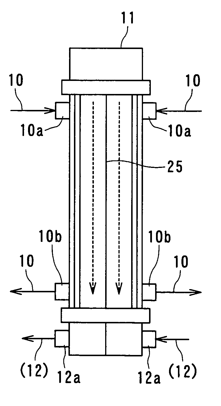
[0059]FIG. 3 represents the illustrated arrangement of the second embodiment of the present invention, which shows a closing state of a nozzle or nozzles 4. In general, nozzles are formed to the bottom portion of the. reactor pressure vessel 1 at portions corresponding to the installation of the internal pumps, and the nozzle 4 has a shape capable of installing the internal pump 3.

[0060] In the arrangement of this embodiment, the ten nozzles 4 are formed to the installation position of the internal pumps 3, and the nozzles 4 corresponding to no location of the internal pumps 3 are closed by closing plates 24 by means of, for example, welding. Further, in a case that requirement of increasing of the internal pumps 3 to be installed is caused in future because of power-up demand, for example, the internal pump 3 can be easily additionally installed and removing the closing plate 24.

[0061] Further, flanges or like members, which are detachably attached by means of bolts, may be utili...

third embodiment

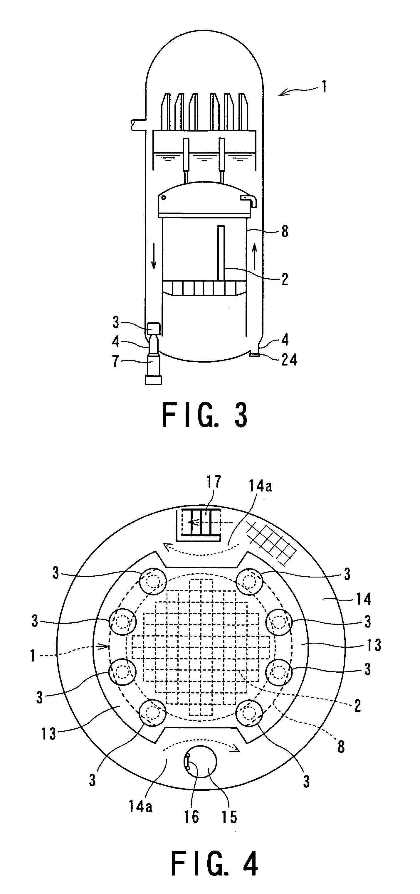
[0062]FIG. 4 shows a sectional view of the lower drywell, representing the third embodiment of the present invention, in which like reference numerals are added to portions or members corresponding to those of the first embodiment and repeated description is omitted herein.

[0063] In this third embodiment, eight internal pumps 3 are installed at eight positions in the ten internal pump installation positions set around the circumferential direction of the bottom portion of the reactor pressure vessel 1, and two internal pumps 3, which are to be installed to opposing two portions, are removed. A passage 14a protruded for maintenance and / or inspection of the internal pump 3 is formed to a walking corridor 14 below the reactor pressure vessel 1 and below either one of the internal pump installation positions at which the internal pumps 3 are not installed. A ladder 16 or stairs 17 are arranged, as access means to the walking corridor 14, near the passage 14a.

[0064] In the structure of...


PUM


Abstract

A nuclear reactor coolant recirculation equipment includes a plurality of internal pumps which are installed around a bottom portion of a reactor pressure vessel of a boiling-light-water reactor, power-supply sections for supplying current to the internal pumps, an internal pump cooling system, for cooling the internal pumps, including cooling water pipes and heat exchangers connected to the cooling water pipes, and auxiliary cooling water pumps for supplying the cooling water to the heat exchangers, respectively. The positions are set as internal pump installation positions at substantially same interval in a circumferential direction around a central portion of the bottom portion of the reactor pressure vessel, and nine or less and four or more numbers of the internal pumps are installed at the ten internal pump installation positions.

Description

BACKGROUND OF THE INVENTION [0001] 1. Field of the Invention [0002] The present invention relates to a reactor coolant recirculation equipment for a boiling water type light water reactor (boiling-light-water reactor) particularly capable of reducing number of coolant recirculation pump accommodated in a nuclear reactor (called internal pump hereinlater) improving safety measure against an accident of power-supply section and simplifying a structure of a cooling water system of the internal pump. [0003] 2. Related Art [0004] In general, a reactor coolant recirculation equipment or system of the boiling water reactor is provided for a reactor pressure vessel, and by forcibly recirculating the coolant to a core in a core shroud, heat or heated steam in the core is removed. In addition, nuclear reactivity of the core is adjusted by changing a flow rate of the reactor coolant, thus controlling a plant power output. [0005] There are known, as reactor coolant recirculation equipment, a so...

Claims


Application Information

Patent Timeline
Patent Type & Authority Applications(United States)
IPC IPC(8): G21C15/00
CPCG21C15/02G21C15/243G21C19/04Y02E30/40G21Y2002/301G21Y2002/40G21Y2004/40G21Y2002/207Y02E30/30
Inventor YAMAZAKI, HIROSHIHISAJIMA, KAZUOISHIBASHI, FUMIHIKOKATAYAMA, KENJIRO
Owner KK TOSHIBA
Why Eureka
Try Eureka