Heat pump with reheat circuit

Active Publication Date: 2006-03-16
CARRIER CORP
View PDF24 Cites 21 Cited by
  • Summary
  • Abstract
  • Description
  • Claims
  • Application Information

AI Technical Summary

Benefits of technology

[0007] In the cooling mode, the reheat coil receives a flow of a relatively hot refrigerant in a vapor, liquid or two-phase state and reheats an airflow (by means of heat transfer interaction with this refrigerant) to a higher temperature than would otherwise be provided by the conventional design schematic. In general, the reheat coil allows for the dehumidified air to be supplied to an environment to be conditioned at a desired temperature. A stream of air is passed over an indoor heat exchanger, which will maintain the air at a low temperature, assuring enough moisture to be removed from the air, but in many cases at a temperature lower than desired in the conditio

Problems solved by technology

This has presented design challenges to refrigerant system designers.
Also, the sys

Method used


Image

  • Heat pump with reheat circuit
  • Heat pump with reheat circuit
  • Heat pump with reheat circuit

Examples


Embodiment Construction

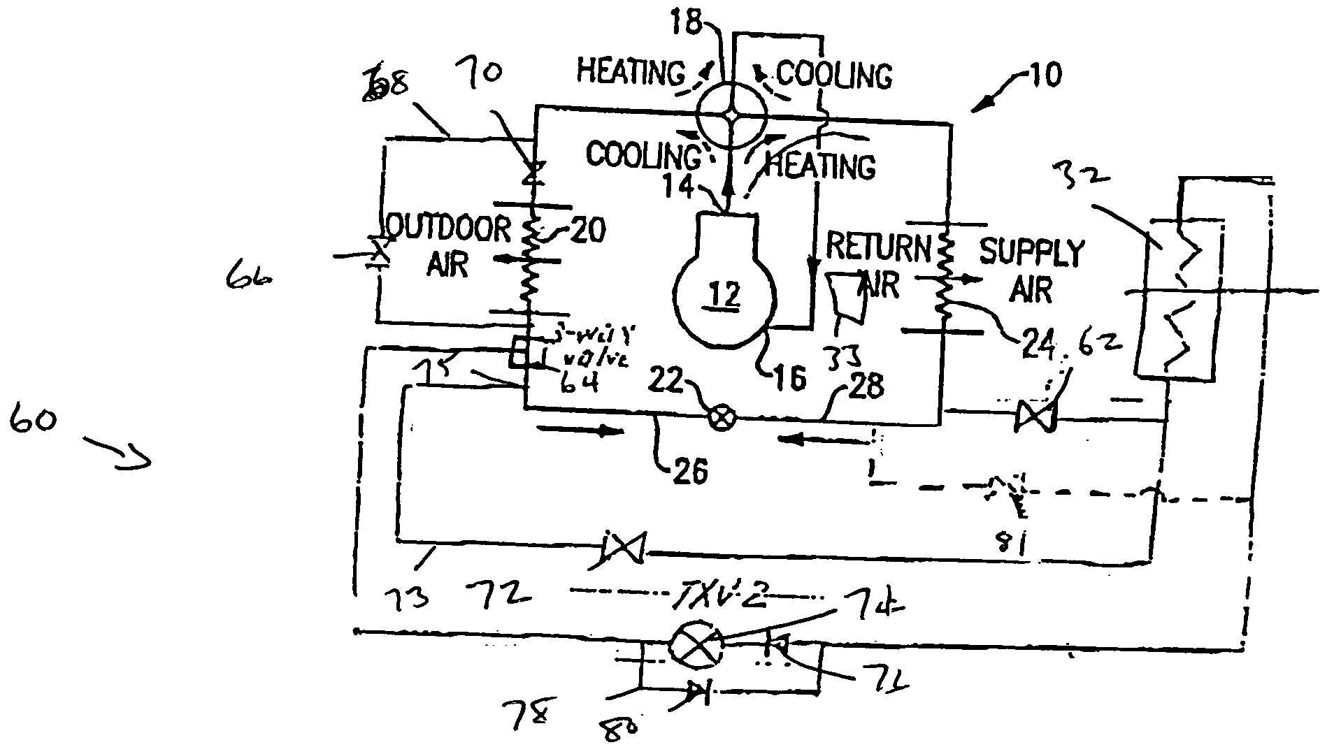
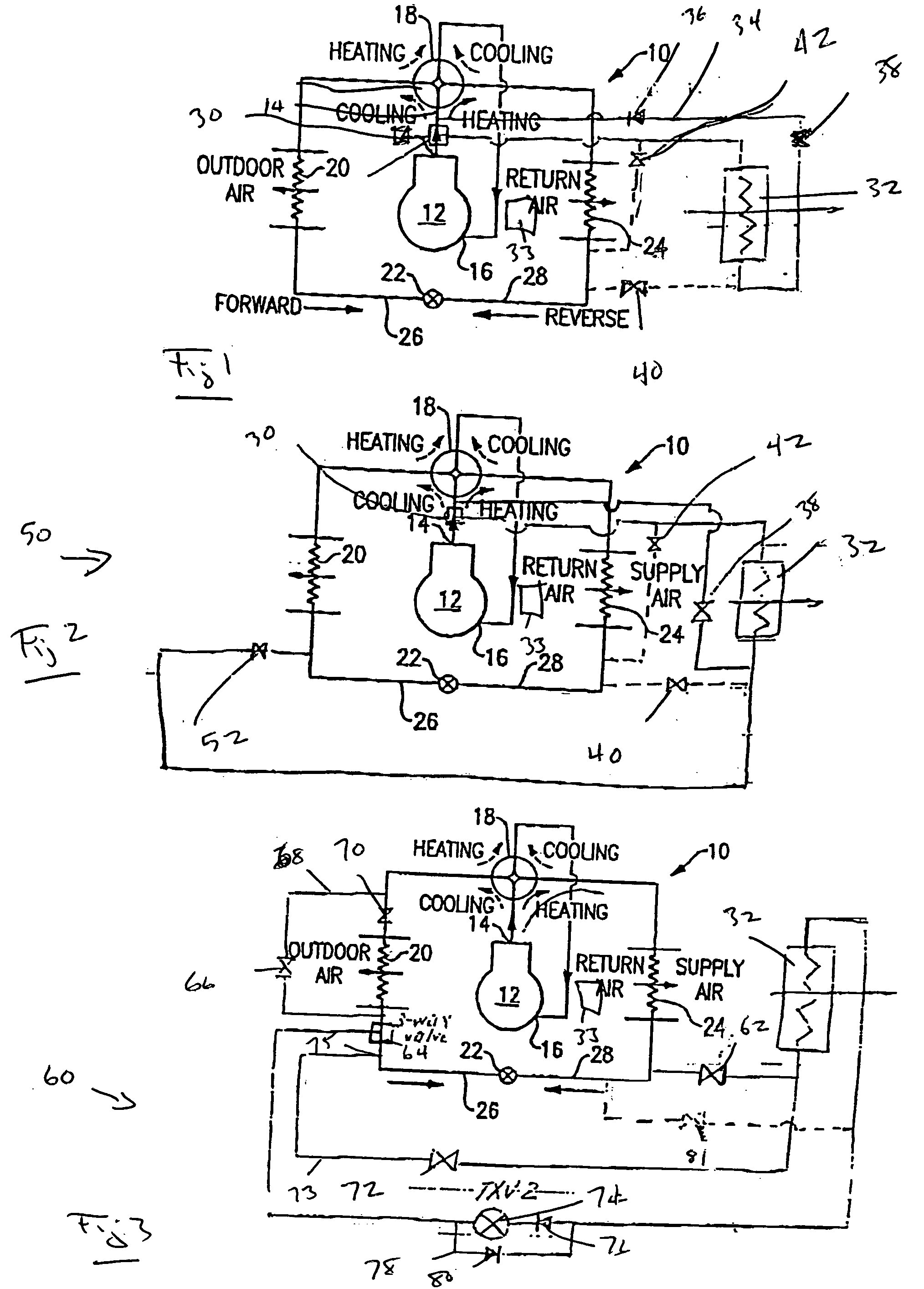
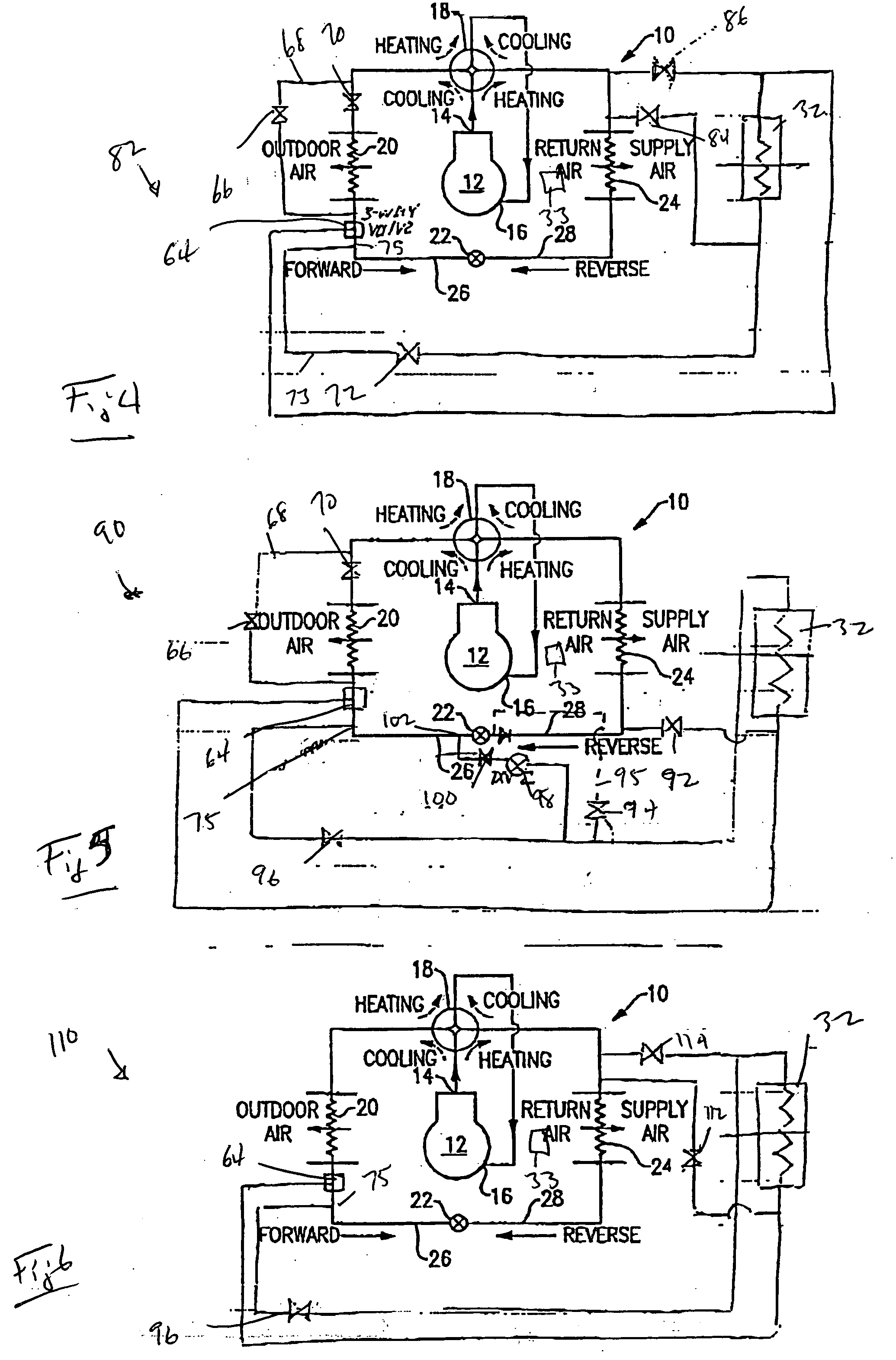
[0018]FIG. 1 shows a heat pump system 10 incorporating a compressor 12 delivering compressed refrigerant to a discharge line 14, and receiving a refrigerant to be compressed from a suction line 16. A main flow control device such as a four-way reversing valve 18 routes the refrigerant to either an outdoor heat exchanger 20 or an indoor heat exchanger 24, as shown, in a cooling or heating mode of operation respectively. In the cooling mode, the refrigerant passes from the discharge line 14 through the four-way reversing valve 18, and downstream to an outdoor heat exchanger 20. Downstream of the outdoor heat exchanger 20 is an expansion device 22, and downstream of the expansion device 22 is an indoor heat exchanger 24. The refrigerant is returned back to the compressor 12 again through the four-way reversing valve 18 and through the suction line 16. In the conventional cooling mode of operation, the air flowing over indoor heat exchanger 24 (an evaporator in this case) is cooled and ...


PUM


Abstract

A refrigerant heat pump system is operable in both heating and cooling modes. A reheat circuit is integrated into the system schematic to provide improved control over temperature and humidity and to cover a wide spectrum of sensible and latent capacity demands. In the heating mode, the reheat coil is utilized to act as a portion of the enlarged indoor heat exchanger (a condenser in this case), in order to enhance system efficiency without the capacity loss. In some cases, where the designer can choose between the efficiency and capacity augmentation, selective operation of the reheat coil may offer an additional step of capacity modulation, in the heating mode. System reliability is improved through a reduction of start/stop cycles. Although various reheat coil arrangements in relation to the indoor and outdoor heat exchangers are offered and reheat concepts are considered, the benefits of the invention are independent from and transparent to such system design features.

Description

BACKGROUND OF THE INVENTION [0001] This invention relates to a heat pump system that is operable in both cooling and heating modes, with a reheat coil incorporated into the system schematic and selectively utilized in both aforementioned modes of operation to provide the benefits of precise temperature and humidity control, performance enhancement, reliability improvement and capacity modulation. [0002] Refrigerant systems are utilized to control the temperature and humidity of air in various indoor environments to be conditioned. In a typical refrigerant system operating in the cooling mode, a refrigerant is compressed in a compressor and delivered to a condenser (or an outdoor heat exchanger in this case). In the condenser, heat is exchanged between outside ambient air and the refrigerant. From the condenser, the refrigerant passes to an expansion device, at which the refrigerant is expanded to a lower pressure and temperature, and then to an evaporator (or an indoor heat exchange...

Claims


Application Information

Patent Timeline
IPC IPC(8): F25B13/00
CPCF24F3/153F25B13/00F25B2500/02F25B2313/02741F25B2400/0405F25B2313/021
Inventor TARAS, MICHAEL F.LIFSON, ALEXANDER
Owner CARRIER CORP
Why Eureka
Try Eureka