Acceleration sensor

a sensor and acceleration technology, applied in the field of acceleration sensors, can solve the problems of sensor shock resistance reduction in the time of sensor falling, inability to anticipate a large amount of power supply, and inability to improve sensitivity electrically, etc., to achieve accurate detection of capacitance variations, facilitate assembly, and facilitate the effect of reaction

Inactive Publication Date: 2006-03-16
HOSIDEN CORP
View PDF3 Cites 12 Cited by
  • Summary
  • Abstract
  • Description
  • Claims
  • Application Information

AI Technical Summary

Benefits of technology

[0029] The case and diaphragm must be electrically connected. The diaphragm has the projections for contacting the case to establish an electrical connection simultaneously with assembly. Thus, this construction facilitates assembly.
[0030] However, the diaphragm could undergo an excessive force applied thereto by a reaction transmitted from the case to the projections, to distort the diaphragm. In this case, the distance between the diaphragm and fixed electrodes could become uneven, thereby affecting accurate detection of variations in capacitance, i.e. detection of acceleration. Thus, the narrow slits are provided to act as buffers having resilience to impart a pressing force for securing the electrical connection to the case and to ease the reaction from the case.
[0031] If the slits were formed simply narrow and linear, a strong force acting on the slits could break the slits per se, or the slits could fail to absorb such a strong force, thereby distorting the diaphragm. The reaction from the case is dynamically the most intensive in the directions perpendicular to the tangents at the points of contact noted above. Where the slits have the semicircular cutouts bulging in the same directions as the projections, the slits have an increased width in the above directions perpendicular to the tangents at the points of contact. As a result, the slits can demonstrate yield strength against an increased reaction.

Problems solved by technology

However, when used as a pedometer, for example, the sensor is in many cases battery-driven, and naturally, abundant power supply cannot be expected.
It is therefore undesirable to improve sensitivity electrically by using an IC (integrated circuit) for amplification which will consume a large amount of current.
However, when the amplitude of the movable electrode is increased in order to increase the force of inertia, the sensor will have reduced shock resistance in time of falling of the sensor.
It is therefore difficult for the basic structure alone shown in Document 1 to cope fully with these problems.

Method used


Image

  • Acceleration sensor
  • Acceleration sensor
  • Acceleration sensor

Examples


Embodiment Construction

[0040] A preferred embodiment of the acceleration sensor according to the present invention will be described hereinafter with reference to the drawings.

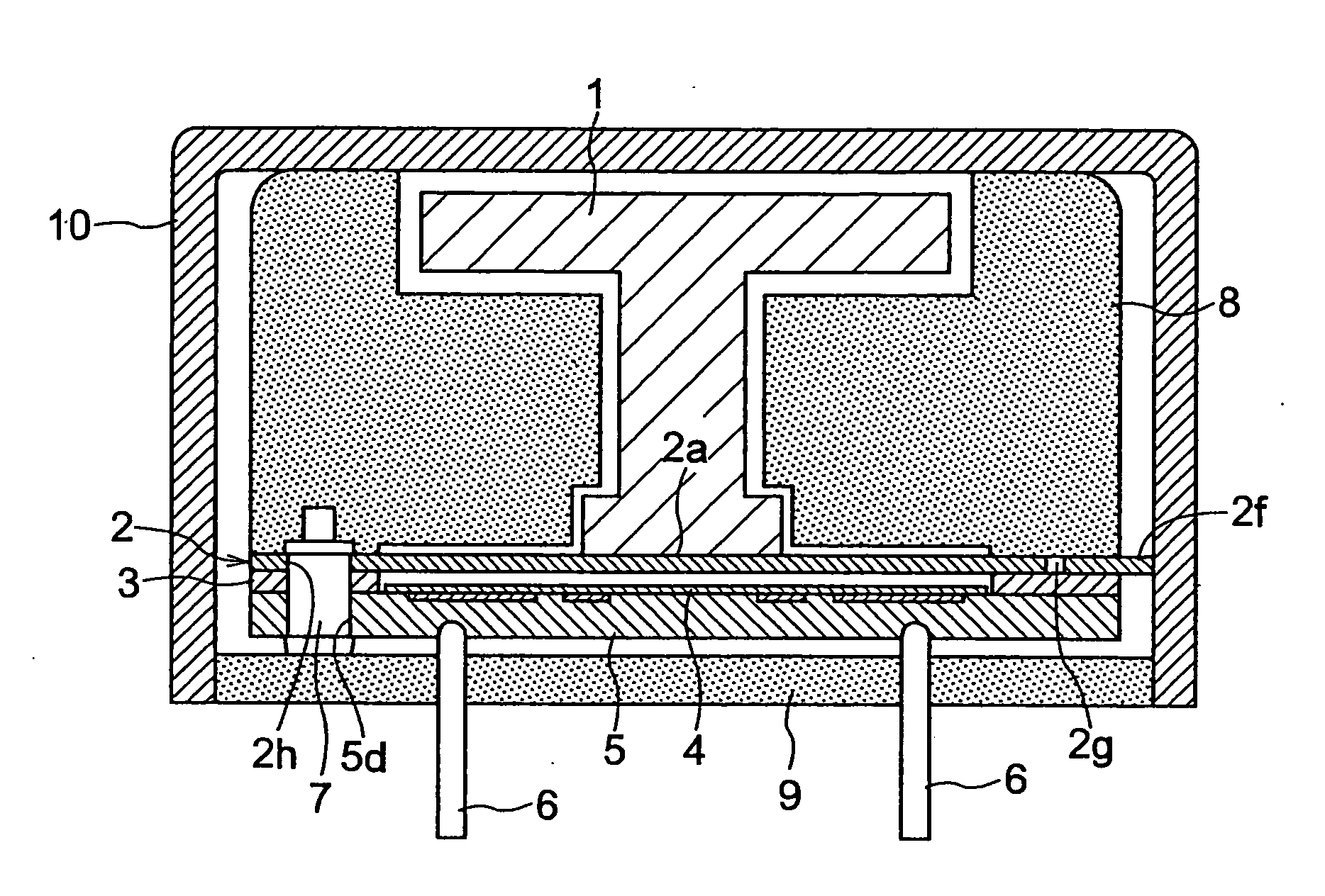
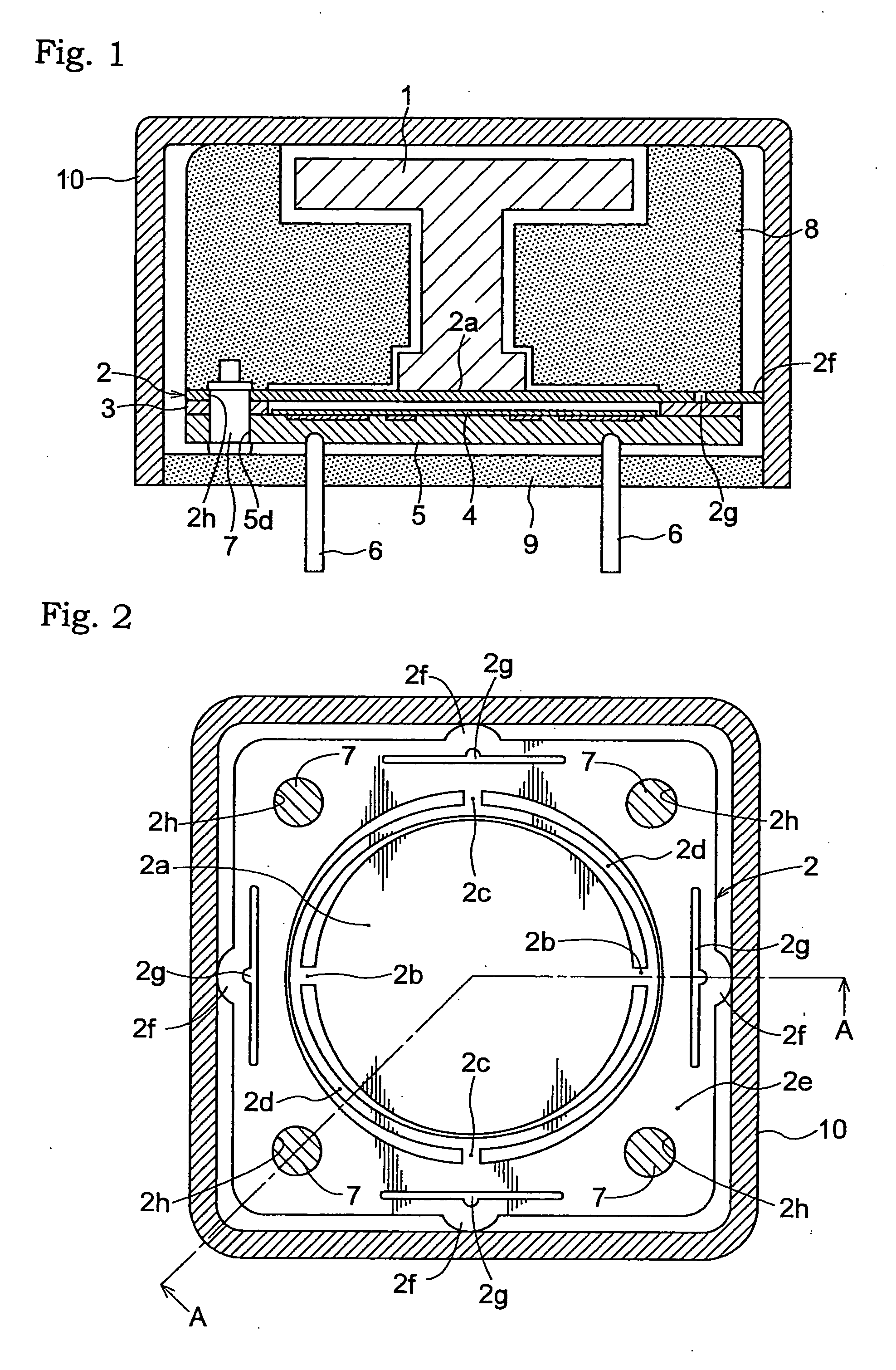
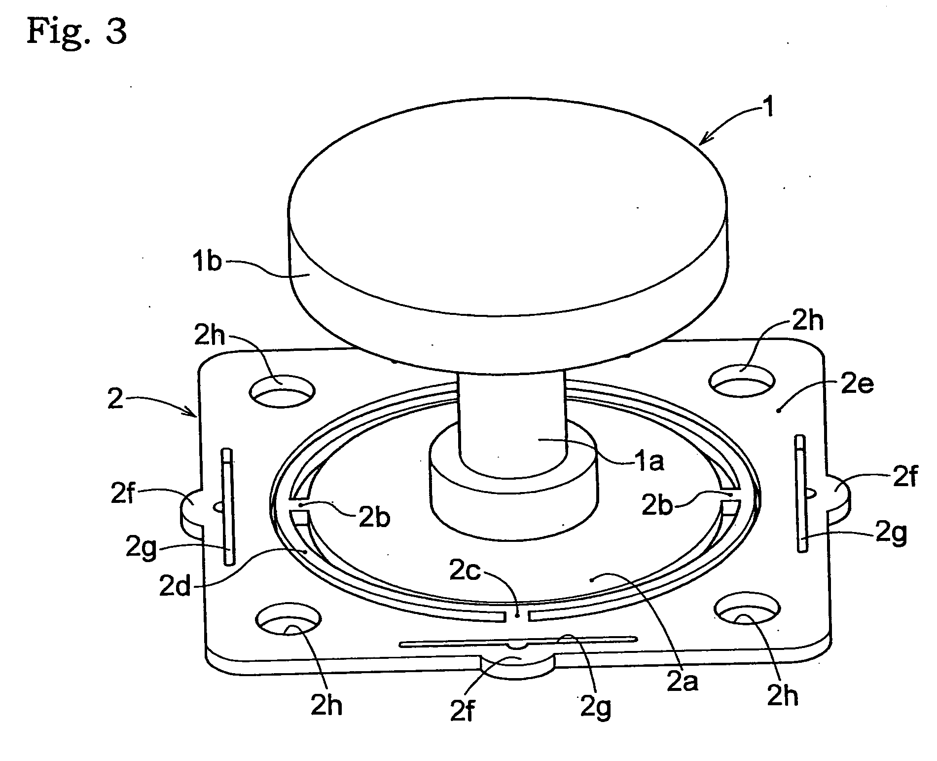
[0041] As shown in FIG. 1, the acceleration sensor according to the invention includes a conductive case 10 of channel-shaped section having a bottom at one end, and an opening at the other end. The case 10 contains an electrode substrate 5 having fixed electrodes on one surface thereof, a diaphragm 2 disposed at a predetermined distance to this electrode substrate 5 across a spacer 3 and having one end thereof opposed to the fixed electrodes and acting as a movable electrode, and a weight 1 disposed centrally of the other surface of the diaphragm 2. The sensor is constructed to detect acceleration in three orthogonal directions based on variations in capacitance between the fixed electrodes (electrode substrate 5) and the movable electrode (diaphragm 2).

[0042] In this embodiment, the case 10 has a rectangular section parallel to ...


PUM


Abstract

A three-axis acceleration sensor having a simple construction is provided for improving shock resistance without lowering sensor sensitivity.
An acceleration sensor for detecting acceleration in three orthogonal directions includes an electrode substrate (5) having fixed electrodes corresponding to three axes, respectively, a diaphragm (2) having one surface thereof opposed to the fixed electrodes acting as a movable electrode, and a weight (1) mounted centrally of the other surface of the diaphragm.
Acceleration is detected based on variations in capacitance between the fixed electrodes and diaphragm (2).
The electrode substrate (5) has an electret layer (4) formed to cover surfaces of the fixed electrodes.

Description

BACKGROUND OF THE INVENTION [0001] 1. Field of the Invention [0002] The present invention relates to an acceleration sensor for detecting acceleration in three orthogonal directions. [0003] 2. Description of the Related Art [0004] Various acceleration sensors have been proposed for detecting acceleration in three-dimensional directions, i.e. along X-axis, Y-axis and Z-axis. Japanese patent application “Kokai” No. 10-10150 cited herein as Document 1 (FIGS. 1 to 3, and paragraphs 7 to 22), for example, discloses an acceleration sensor for detecting acceleration based on variations in capacitance between a fixed electrode and a movable electrode opposed to each other. According to this technique, one of the fixed electrode and movable electrode has an electret film formed on a surface thereof opposed to the other electrode. The movable electrode has a weight attached to a surface thereof facing away from the fixed electrode to allow for displacement of the movable electrode in time of ...

Claims


Application Information

Patent Timeline
Patent Type & Authority Applications(United States)
IPC IPC(8): G01P15/00G01P15/125G01P15/18
CPCG01H11/06G01P15/18G01P15/125G01P1/023G01P15/12
Inventor SUGIMORI, YASUOTOYOTA, NAOKI
Owner HOSIDEN CORP
Why Eureka
Try Eureka