
Solid sandstone dissolver

Inactive Publication Date: 2006-03-16
SCHLUMBERGER TECH CORP
View PDF9 Cites 31 Cited by
  • Summary
  • Abstract
  • Description
  • Claims
  • Application Information

AI Technical Summary

Benefits of technology

[0010] One embodiment is a water-free composition that contains particles of a solid acid-precursor and particles of a solid that releases hydrogen fluoride in the presence of aqueous acid. Examples of the solid acid-precursor are lactide, glycolide, polylactic acid, polyglycolic acid, copolymers of polylactic acid and polyglycolic acid, copolymers of glycolic acid with other hydroxy-, carboxylic acid-, or hydroxycarboxylic acid-containing moieties, copolymers of lactic acid with other hydroxy-, carboxylic acid-, or hydroxycarboxylic acid-containing moieties, and mixtures of these materials. The solid acid-precursor may be encapsulated or may be coated with an effective amount of a material that slows hydrolysis of the solid acid-precursor when it is contacted with

Problems solved by technology

There are generally three major problems encountered during this normal procedure.
First, in the pumping operation the acid is in contact with iron-containing components of the wellbore such as casing, liner, coiled tubing, etc.
Strong acids are corrosive to such materials, especially at high temperature.
Furthermore, acid corrosion creates iron compounds such as iron chlorides.
These iron compounds may precipitate, especially if sulfur or sulfides are present, and may interfere with the stability or effectiveness of other components of the fluid, thus requiring addition of iron control agents or iron sequestering agents to the fluid.
Second, if, as is usually the case, the intention is to use the acid to treat parts of the formation at a significant distance away from the wellbore (usually in addition to treating parts of the formation nearer the wellbore), this may be very difficult to accomplish because if an acid is injected from the surface down a wellbore and into contact with the formation, the acid will naturally react with the first reactive material with which it comes into contact.
At best this may be wasteful of acid; at worst this may make the treatment ineffective or even harmful.
In general, the higher the temperature the more reactive is the acid and the greater are the problems.
This is usually a severe problem when at least some of the formation is carbonate, which is typically very reactive towards acid.
Third, even when the acid has successfully been contacted with the desired region of the fracture face, there is sometimes a tendency for the acid to react evenly with the fracture faces, especially in localized regions, so that conductive channels along the fracture faces are not created by differential etching in such regions after fracture closure.
There are problems with these methods.
Although emulsified acids are popular and effective, they require additional additives and specialized equipment and expertise, and may be difficult to control.
A problem with the encapsulated acids is that the location and timing of release of the acid may be difficult to control.
Physical damage to the encapsulating material, or incomplete or inadequate coating during manufacture, could cause premature release of the acid.

Method used


Image

  • Solid sandstone dissolver
  • Solid sandstone dissolver
  • Solid sandstone dissolver

Examples


example 1

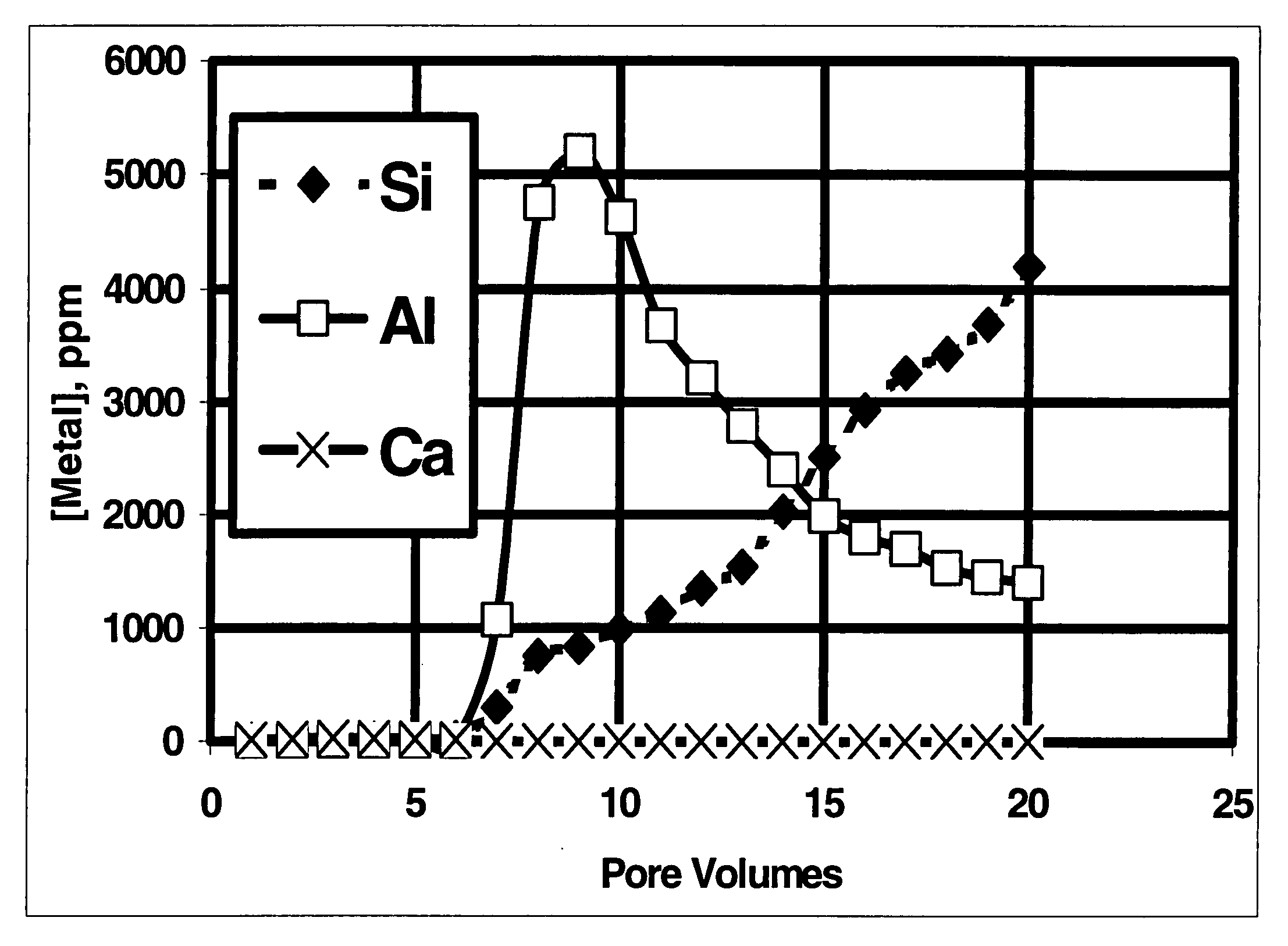
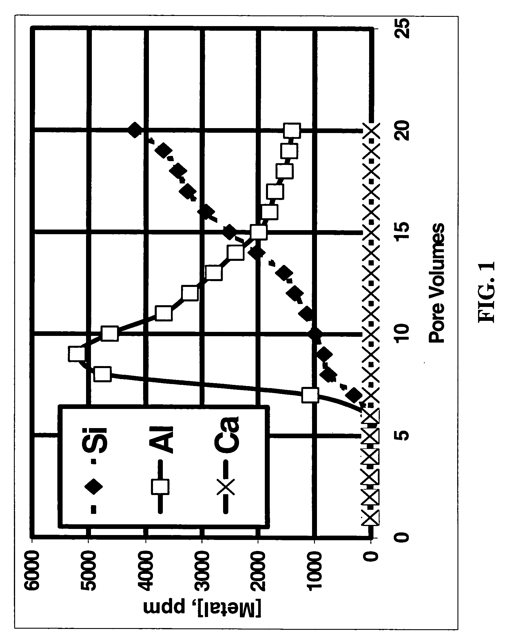
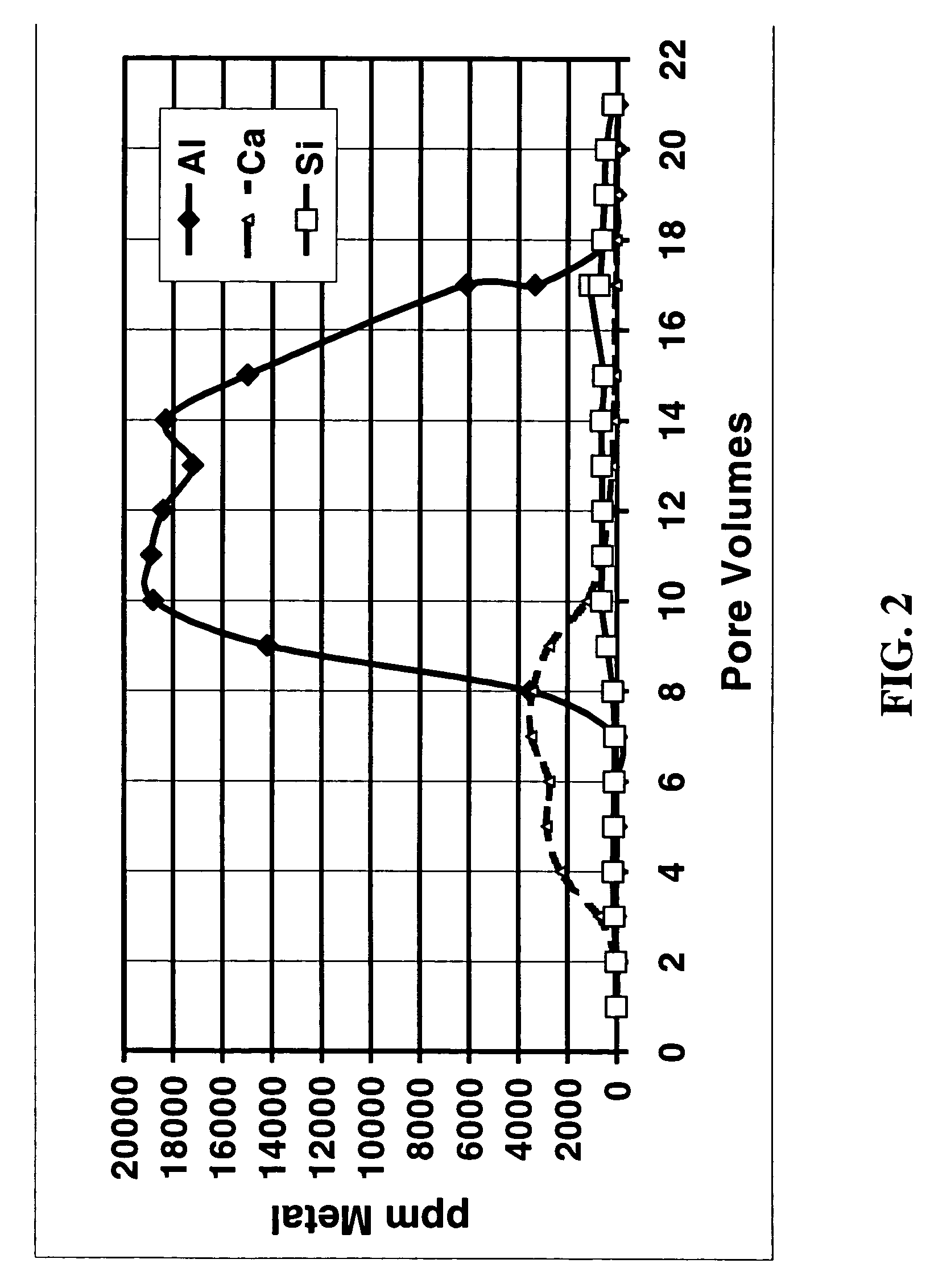
[0047] To simulate the effects of acid fracturing with a slurry of polylactic acid and ammonium bifluoride, a fluid containing 10% lactic acid (the hydrolysis / dissolution product of polylactic acid) and 4% ammonium bifluoride was injected into a 2.5 cm by 15.2 cm Berea sandstone core at 350° F. (177° C.) at a flow rate of 2.5 ml / min with a confining pressure of 6.9 MPa and a back pressure of 10.3 MPa. FIG. 1 shows a plot of different metal concentrations measured in the effluent fluid as a function of the total fluid volume pumped during a single core flow experiment. The fluid was collected at the outlet of the core flow equipment and was analyzed by ICP. The steady increase in Si concentration is a clear indication that, in combination with a fluoride-containing fluid, the polylactic acid hydrolysis product dissolved a significant amount of silicates from the sandstone. For comparison, FIG. 2 shows the results when a fluid that was 10% acetic acid in 9 / 1 mud acid was pumped throug...

example 2

[0048]FIGS. 3 and 4 show a core flow experiment in which a split sandstone core was used and the affect of inert masking material was simulated. FIG. 3A shows the core with masking material in place, and FIG. 3B shows the core after etching. The 2.5 cm×15 cm inch core was cut in half along the core length; one half is shown as [12]. Teflon fibers [8] (about 0.08 cm×about 15 cm) were placed between the two pieces as shown in FIG. 3A. The pieces were then reassembled and loaded into a core holder, and a confining pressure of 13.8 MPa was applied. FIG. 4 shows the permeability when several fluids were injected into the gap between the two sandstone pieces in the core holder. A 5% ammonium fluoride solution was injected (triangles before about 7 min.) at a flow rate of 5 cc / min, then 12 / 6 mud acid at the same flow rate 9squares), and then 5% ammonium fluoride again at the same flow rate (triangles after about 17.5 min.). The permeability was clearly higher after the treatment of this si...

example 3

[0050]FIG. 5 shows a schematic of how a fracture would appear if created by the method of the invention. The fracture [4] in the formation [2] contains regions [6] that are not open to fluid flow. These regions are where the inert or reactive masking material is trapped when the fracture closes. The fracture face is protected from the formation dissolving agent at those locations.


PUM


Abstract

A dry solid composition is disclosed that, when added to an aqueous liquid, provides a slurry that can be used in sandstone acid fracturing. The slurry generates hydrofluoric acid downhole to etch the sandstone fracture faces created. The chemical and physical properties of the composition result in very uneven etching of the fracture faces, enhancing the fluid conductivity of the final fracture. Optionally, inert masking materials may be included in the dry composition, or added to the slurry, to increase the inhomogeneity of the etching and further increase the fluid conductivity.

Description

[0001] This application is a Continuation-in-Part of U.S. patent application Ser. No. 10 / 605,784, filed on Oct. 27, 2003, which claimed the benefit of U.S. Provisional Patent Application No. 60 / 421,696, filed on Oct. 28, 2002. This application is related to a U.S. patent application Ser. No. 10 / 941,384 entitled “Selective Fracture Face Dissolution,” filed on Sep. 15, 2004, inventors J. Ernest Brown, et al., and to a U.S. patent application Ser. No. 10 / 941,385 entitled “Differential Etching in Acid Fracturing,” filed on Sep. 15, 2004, inventors J. Ernest Brown, et al.BACKGROUND OF THE INVENTION [0002] The invention relates to stimulation of wells penetrating subterranean formations. In particular it relates to acid fracturing; more particularly it relates to methods of etching the fracture faces so that etching is minimal in some regions but a conductive path from the fracture tip to the wellbore is nonetheless created. Most particularly it relates to a solid additive that is added t...

Claims


Application Information

Patent Timeline
IPC IPC(8): E21B43/26
CPCC09K8/62
Inventor BROWN, J. ERNESTSTILL, JOHN W.FU, DIANKUIXIAO, ZHIJUNFRENIER, WAYNE
Owner SCHLUMBERGER TECH CORP
Learn More