Vortex enhanced filtration device and methods

a filtration device and filtration method technology, applied in centrifuges, separation processes, membranes, etc., can solve the problems of limiting the problem of filtration, filter clogging, and filtration performance decline, and achieve the effect of reducing concentration polarization

Active Publication Date: 2006-03-16
MCLAUGHLIN TRUSTEE OF THE JENNIFER MCLAUGHLIN TRUST JENNIFER K
View PDF28 Cites 78 Cited by
  • Summary
  • Abstract
  • Description
  • Claims
  • Application Information

AI Technical Summary

Benefits of technology

[0017] A method is disclosed in accordance with another embodiment of the present invention for filtering a solution and/or suspension to separate soluble and/or insoluble materials from a liquid filtrate. The method comprises the steps of: (1) providing a device comprising a cylindrical housing having at least one inlet port and at least one filtrate port, a cylindrical rotor adapted to rotate within the housing, the rotor having a rotational drive means comprising a plurality of turbine vanes, and a filtration membrane affixed to the rotor or the housing, between the at l...

Problems solved by technology

One of the most limiting problems in filtration is filter clogging, scientifically described as “concentration polarization.” As a result of the selective permeability properties of the filter, the filtered material that cannot pass through the filter becomes concentrated on the surface of the filter.
Consequently, filtrate flux is reduced and filtration performance diminishes.
Taylor-Couette filtration devices generate strong vorticity as a result of centrifugal flow instability (“Taylor instability”), which serves to mix the filtered material concentrated along the filter back into the fluid to be processed.
It has been observed that membrane fouling due to concentration polarization is very slow compared to dead-end or tangential filtration.
Further, these separators only had to operate for relatively s...

Method used


Image

  • Vortex enhanced filtration device and methods
  • Vortex enhanced filtration device and methods
  • Vortex enhanced filtration device and methods

Examples


Embodiment Construction

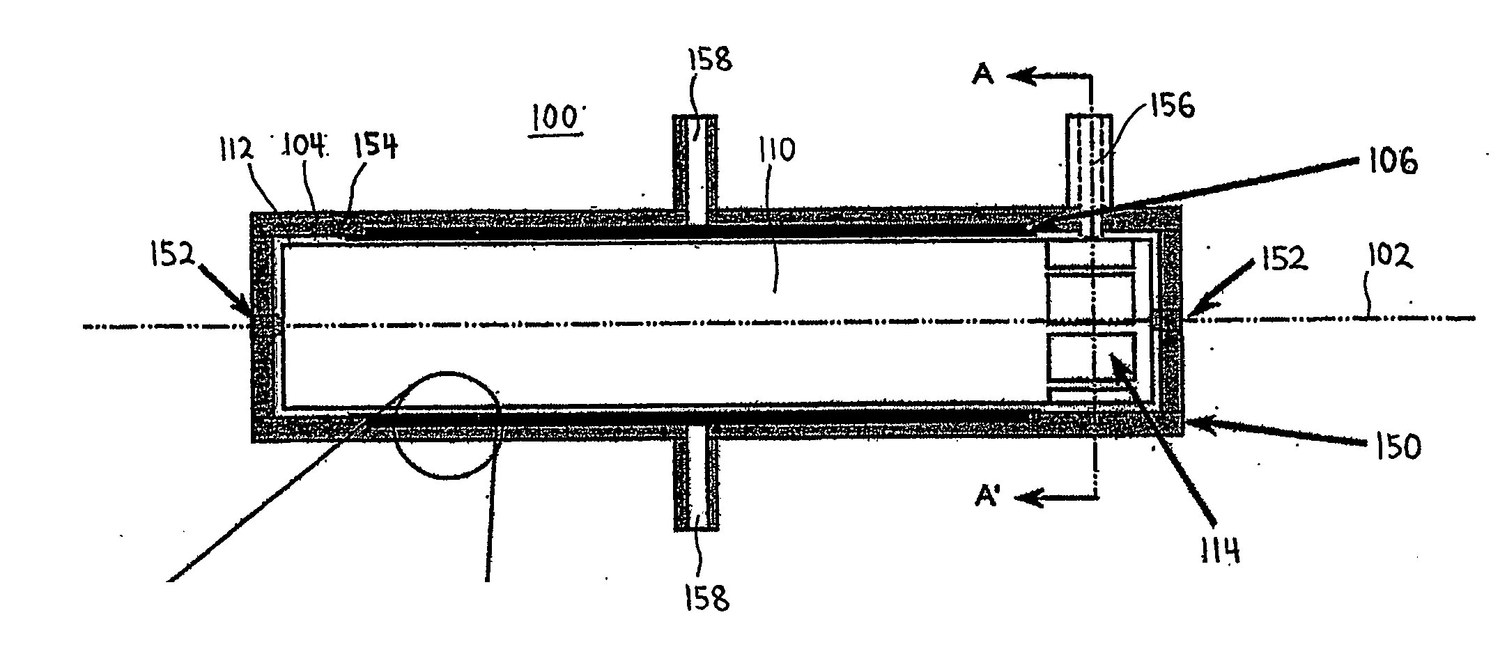
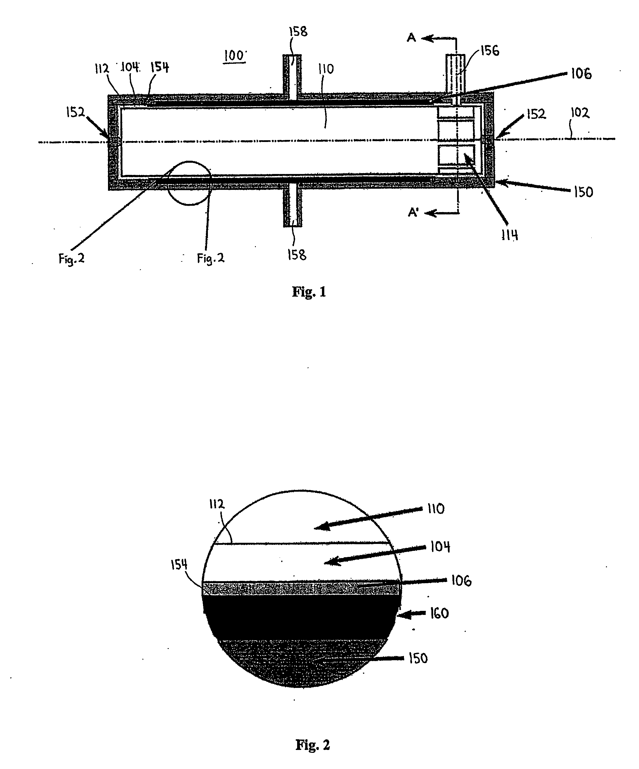
[0029]FIG. 1 is a sectional view of the rotational filtration device 100 according to one embodiment of the present invention. The sectional view shows the housing 150 of the rotational filtration device bisected along line A-A′, but the rotor 110 is shown intact. The rotational filtration device 100 comprises a rotor 110 arranged coaxially within the bore of a housing 150. In the illustrated embodiment both the rotor 110 and the bore are cylindrical. In one embodiment the rotor 110 is mounted on two posts 152 within the housing 150 along the central axis 102 of the rotational filtration device 100. These posts limit both the axial and the radial motion of the rotor 110. There is a gap 104 between the outer wall 112 of the rotor 110 and the inner wall 154 of the housing 150. The gap 104 extends evenly around the rotor 110. In another embodiment the posts 152 are not used and the rotor 110 is suspended within the housing 150 solely by the flow of process fluid through the gap 104.

[0...


PUM

PropertyMeasurementUnit
Pressureaaaaaaaaaa
Flow rateaaaaaaaaaa
Diameteraaaaaaaaaa

Abstract

Preferred aspects of the present invention relate to advances in rotating, vortex-enhanced reverse osmosis filtration. More particularly, the filtration device and methods incorporate a rotational drive mechanism adapted to use the flow of pressurized process fluid to cause rotation of a rotor within a housing, thereby creating shear and Taylor vortices in the gap between the rotor and housing. The improvements disclosed herein facilitate continuous use of vortex-enhanced filtration for prolonged periods of time.

Description

BACKGROUND OF THE INVENTION [0001] 1. Field of the Invention [0002] Preferred aspects of the present invention relate to rotating reverse osmosis (RO) filtration, wherein filtrate flux is enhanced by creation of shear and Taylor vortices in the coaxial gap between a RO membrane and a cylindrical wall of the filtration device. [0003] 2. Description of the Related Art [0004] One of the most limiting problems in filtration is filter clogging, scientifically described as “concentration polarization.” As a result of the selective permeability properties of the filter, the filtered material that cannot pass through the filter becomes concentrated on the surface of the filter. This phenomenon is clearly illustrated in the case of a “dead-end” filter, such as a coffee filter. During the course of the filtration process, the filtered material (coffee grounds) building up on the filter creates flow resistance to the filtrate, the fluid (coffee) which can pass through the filter. Consequently,...

Claims


Application Information

Patent Timeline
IPC IPC(8): B01D63/16B01D29/11B01D29/86F04D29/24B01D33/68B01D61/02B01D61/08B01D61/10B01D61/14B01D61/24B01D65/08B01D69/10C02F1/00C02F1/38C02F1/44
CPCB01D29/117B01D61/025C02F2301/024B01D61/027B01D61/10B01D63/06B01D63/16B01D65/08B01D2315/02B01D2321/2016B01D2321/2033C02F1/38C02F1/44C02F1/441C02F1/442C02F1/444C02F2103/08B01D29/906Y02A20/131B01D63/069
Inventor SCHOENDORFER, DON
Owner MCLAUGHLIN TRUSTEE OF THE JENNIFER MCLAUGHLIN TRUST JENNIFER K
Why Eureka
Try Eureka