Metallic electrolytic cell and metal electrolysis process

A technology of metal electrolysis and electrolytic cell, which is applied in the field of metal electrolysis process and metal electrolytic cell, and can solve problems such as cell voltage increasing production energy consumption, product quality declining, and affecting anode slime settlement, etc.

Active Publication Date: 2015-03-11
YANGGU XIANGGUANG COPPER
View PDF5 Cites 20 Cited by
  • Summary
  • Abstract
  • Description
  • Claims
  • Application Information

AI Technical Summary

Problems solved by technology

[0011] However, since the liquid inlet 02 is located on the same side of the tank body, that is, the metal electrolytic cell enters liquid from one side, and when the electrolyte moves from one side of the tank body 01 to the other side, the side opposite to the liquid inlet 02 and the electrolytic cell Electrolyte flow in the upper part is slower
When the current density increases, the dissolution rate of metal ions on the anode is accelerated, and the precipitation rate of metal ions on the cathode is accelerated. Because the circulation rate of the electrolyte is too slow, the concentration difference of metal ions between the two plates cannot be reduced in time, resulting in the quality of the cathode plate. The increase in voltage will seriously cause a series of problems such as anode passivation, which not only affects the normal production, but also greatly increases the energy consumption of production.
[0012] At the same time, the existing technology adopts the bottom-in and top-out circulation method, so that the electrolyte circulation direction is opposite to the anode sludge settlement direction. If the electrolyte circulation volume is increased, the anode sludge settlement will inevitably be affected. In severe cases, the electrolyte solution will be turbid, causing a large number of anode sludge Mud is mechanically attached to the cathode plate, resulting in a decline in product quality

Method used


Image

  • Metallic electrolytic cell and metal electrolysis process
  • Metallic electrolytic cell and metal electrolysis process
  • Metallic electrolytic cell and metal electrolysis process

Examples


Embodiment Construction

[0036] The core of the present invention is to provide a metal electrolytic cell with reduced concentration polarization. Another core of the present invention is to provide a metal electrolysis process.

[0037]In order to enable those skilled in the art to better understand the technical solutions of the present invention, the present invention will be further described in detail below in conjunction with the accompanying drawings and embodiments.

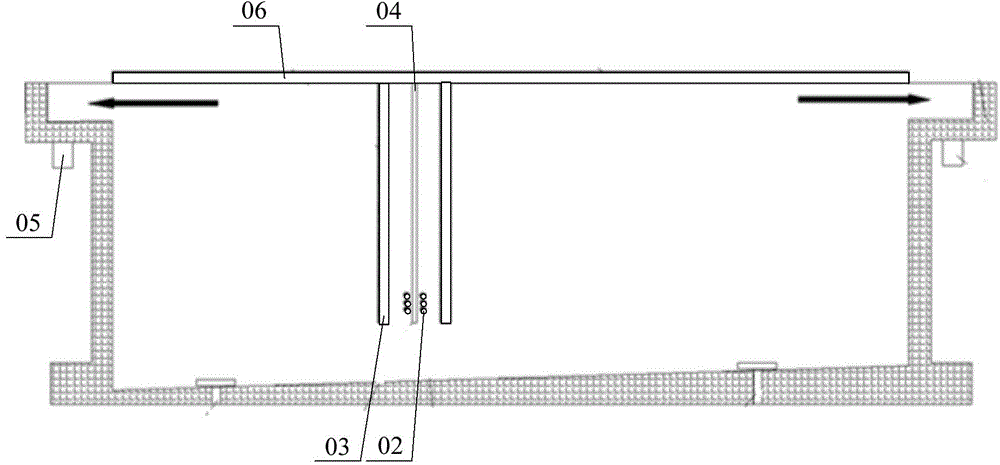
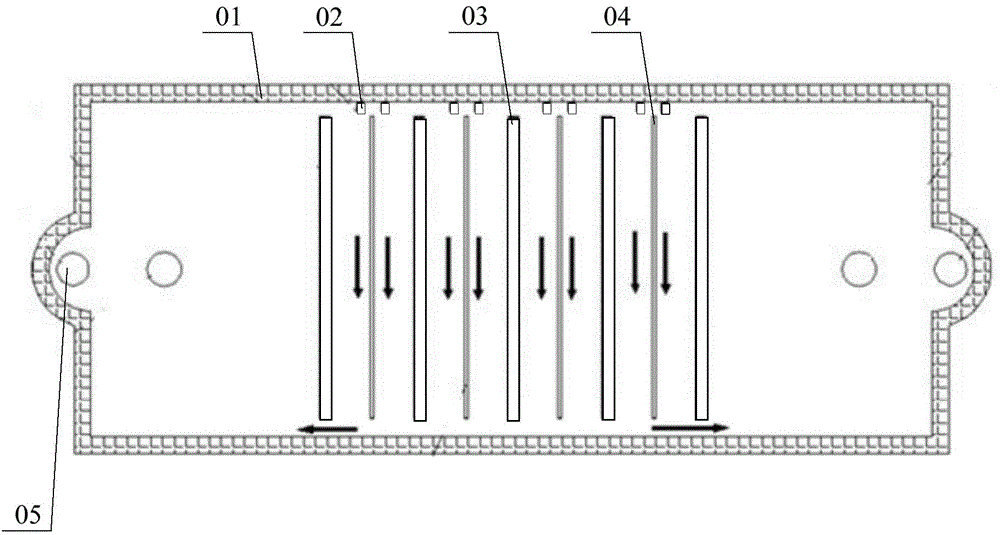
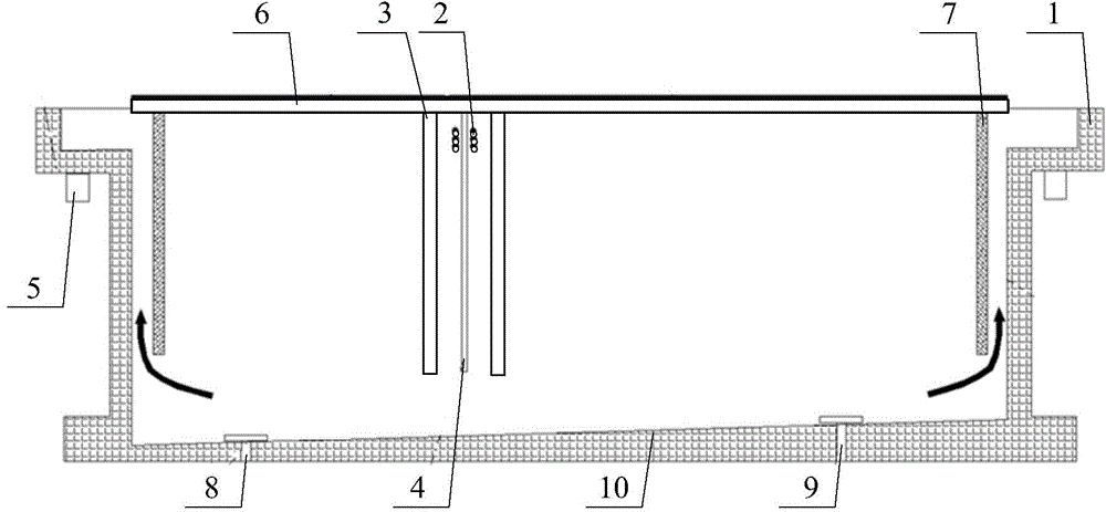
[0038] Please refer to Figure 3 to Figure 6 , in a specific embodiment, the metal electrolytic cell provided by the present invention includes a cell body 1, a conductive row 6, an anode plate 3, a cathode plate 4, and arc-shaped liquid-guiding protrusions 11 installed at opposite ends of the cell body 1, specifically Yes, preferably, the arc of the arc-shaped liquid guiding protrusion 11 is 60° to 180°, specifically, the arc of the arc-shaped liquid guiding protrusion 11 is 75°. Both ends of the cathode plate 4 abut against t...


PUM

PropertyMeasurementUnit
angleaaaaaaaaaa

Abstract

The invention discloses a metallic electrolytic cell which comprises a cell body, anode plates, cathode plates and arc-shaped drainage bulges, wherein the arc-shaped drainage bulges are mounted at the two opposite ends of the cell body; the anode plates and the cathode plates are alternatively arranged in the cell body, and liquid inlets and overflow openings are formed in the cell body; the liquid inlets in the two sides of each cathode plate are positioned in the same end of the cathode plate, and the liquid inlets in the two sides of each anode plate are respectively positioned in the two ends of the anode plate; the two ends of each cathode plate are respectively butted with the convex ends of the arc-shaped drainage bulges, and a liquid drainage cavity is formed between the cathode plates and the arc-shaped drainage bulges. Two adjacent cathode plates and one anode plate between the cathode plates form a similar closed space, electrolyte is fast ejected to enter the space through the liquid inlets in one end of one cathode plate and the other end of the adjacent cathode plate, and then the electrolyte flows clockwise and anticlockwise. The kinetic energy of electrolyte is utilized, the concentration difference of metal ions between the two pole plates is greatly reduced, and the concentration polarization is effectively reduced. The invention further discloses a metal electrolysis process.

Description

technical field [0001] The invention relates to the technical field of material extraction, in particular to a metal electrolytic cell. The invention also relates to a metal electrolysis process. Background technique [0002] The metal electrolytic cell is mainly used for the electrolysis of copper, lead, nickel and other metals and the purification of the electrolyte. For example, the traditional copper smelting is to obtain anode copper after the mineral raw material copper concentrate is smelted, blown, and pyro-refined. The anode copper is electrolytically refined in the metal electrolytic bath to obtain electrolytic copper, and the purity of copper is improved. [0003] Electrolytic refining is the main means of metal refining in the process of non-ferrous metal smelting, and it is also a final link of non-ferrous metal smelting. The advanced technology and supporting equipment directly affect the quality of metals and the level of production capacity. The electrolys...

Claims


Application Information

Patent Timeline
Patent Type & Authority Applications(China)
IPC IPC(8): C25C7/00C25C7/06C25C1/12
CPCY02P10/20
Inventor 高俊江杨加桂
Owner YANGGU XIANGGUANG COPPER
Why Eureka
Try Eureka