Organic electroluminescent element

Active Publication Date: 2006-03-16
UDC IRELAND
View PDF7 Cites 25 Cited by
  • Summary
  • Abstract
  • Description
  • Claims
  • Application Information

AI Technical Summary

Benefits of technology

[0010] The present invention was achieved in view of the above-mentioned situations and provides a blue phosphoresce

Problems solved by technology

One important problem in an organic electroluminescent element is a problem of development of a blue phosphorescent organic electroluminescent element (hereinafter, referred to as “blue phosphorescent luminescent element” for convenience).
However, the blue phosphorescent luminescent element disclosed in the literature is not sufficiently high in the luminous efficiency and the dri

Method used


Image

  • Organic electroluminescent element
  • Organic electroluminescent element
  • Organic electroluminescent element

Examples


example 1

1. Preparation of Organic Electroluminescent Element

(1) Preparation of an Example Organic Electroluminescent Element (TC-11)

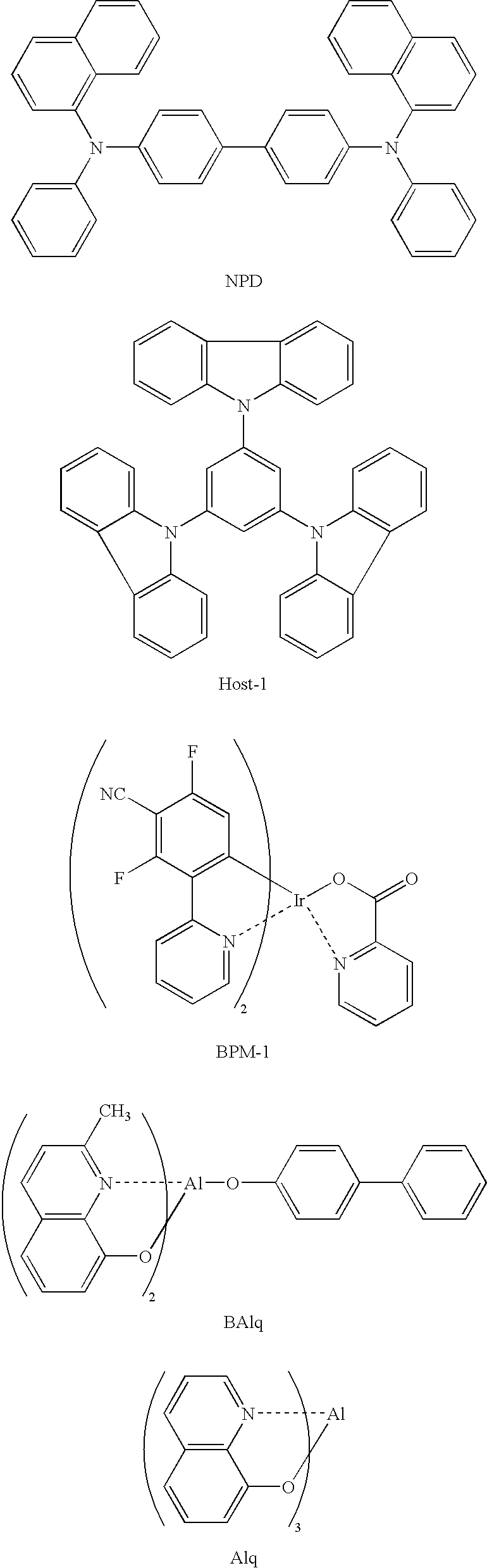
[0098] A 2.5 cm square and 0.5 mm thick glass substrate with an ITO film (surface resistivity: 10 Ω / sq., manufactured by Geomatec Co., Ltd.) was put into a washing vessel, washed in 2-propanol by applying ultrasonic, followed by subjecting to a UV-ozone process for 30 min. On the transparent anode (ITO film), by use of a vacuum deposition method, organic compound layers below were sequentially deposited.

[0099] The deposition speed in the examples according to the invention, unless otherwise mentioned, was 0.2 nm / min. The deposition speed was measured with a quartz oscillator. Thicknesses of the layers described below were also measured with a quartz oscillator.

[0100] Values of the ionization potentials and electron affinities of the respective organic compound layers in the TC-11 are described together in configurations of the respective layers.

(First H...


PUM

PropertyMeasurementUnit
Molecular strain energyaaaaaaaaaa
Bond energyaaaaaaaaaa
Energyaaaaaaaaaa

Abstract

The present invention provides an organic electroluminescent element that includes a pair of electrodes and a plurality of organic compound layers being disposed between the pair of electrodes. The organic compound layers include a luminescent layer containing a blue phosphorescent luminescent material and a host material having the lowest excited triplet energy (T1) of 272 kJ/mol (65 kcal/mol) or more, and hole transport layers. One of the hole transport layers is a layer adjacent to the luminescent layer, and when the ionization potentials of the luminescent layer, the hole transport layer adjacent to the luminescent layer, and another of the hole transport layers, respectively, designated to Ip1, Ip2 and Ip3, the relationship Ip1>Ip2>Ip3 is satisfied.

Description

CROSS-REFERENCE TO RELATED APPLICATION [0001] This application claims priority under 35 USC 119 from Japanese Patent Applications Nos. 2004-268559 and 2005-060877, the disclosures of which are incorporated by reference herein. BACKGROUND OF THE INVENTION [0002] 1. Field of the Invention [0003] The present invention relates to an organic electroluminescent element that converts electric energy to light and luminesce. [0004] 2. Description of the Related Art [0005] An organic electroluminescent element is made of an organic compound layer that includes at least a luminescent layer and a pair of electrodes that sandwich the organic compound layer. When an electric field is applied between both electrodes, electrons are injected from a cathode and holes are injected from an anode. The electrons and holes recombine in a luminescent layer to luminesce. [0006] One important problem in an organic electroluminescent element is a problem of development of a blue phosphorescent organic electro...

Claims


Application Information

Patent Timeline
IPC IPC(8): H05B33/12
CPCH01L51/0057H01L51/0061H01L51/0071H01L51/0072Y10S428/917H01L51/50H01L51/5016H01L51/5048Y10T428/24942H01L51/0094H10K85/625H10K85/636H10K85/6572H10K85/657H10K85/40H10K50/14H10K50/11H10K2101/10H10K50/00
Inventor TSUKAHARA, JIROIGARASHI, TATSUYAISE, TOSHIHIROKITAMURA, YOSHITAKA
Owner UDC IRELAND
Why Eureka
Try Eureka