Eureka AIR delivers breakthrough ideas for toughest innovation challenges, trusted by R&D personnel around the world.

Dynamic power control circuit of wireless communication device

Active Publication Date: 2006-03-16
INVENTEC APPLIANCES CORP
View PDF4 Cites 5 Cited by
  • Summary
  • Abstract
  • Description
  • Claims
  • Application Information

AI Technical Summary

Benefits of technology

[0010] It is an object of the present invention to provide a dynamic power control circuit to reduce the power consumption and increase speaking time of a wireless communication device. The wireless communication device comprises a radio frequency (RF) auto-gain control circuit. The auto-gain control circuit includes a dynamic gain power amplifier, a power detector, a comparator, and a low pass filter, wherein another power detector, another comparator, another low pass filter and an adder are disposed between the comparator and the antenna of the wireless communication device. A reference voltage is imposed on the adder, so as to enable the another power detector to detect the signal voltage received from the antenna, and output the received voltage to the another comparator. The another comparator compares the received voltage with a specified received voltage limit, and outputs a reference voltage to the another low pass filter. The another low pass filter filters out the noise of the reference voltage and outputs the reference voltage to the adder. The adder adds the reference voltage and the specified reference voltage, and outputs the result to the comparator. In this manner, the auto-gain control circuit can control the output power corresponding to the strength of the received signals. When the received signal is weak, the output power accordingly is increased, so as to enhance the phone connecting quality. When the received signal is strong, the output power accordingly is reduced, so as to decrease power consumption and increase the speaking time on the phone.

Problems solved by technology

The capacity of the conventional lithium battery no longer sustains the normal usage of the wireless communication device, especially for the wireless fidelity (Wi-Fi) communication devices.
Since the Wi-Fi communication device occurs a lot of power consumption, it is deemed necessary to develop low power consumption Wi-Fi communication devices.
On the contrary, if the output power reaches 15 dBm, Vc will become negative, which will decrease the power amplification gain.
This gives rise to a poor talk quality when the signals are weaker (or even no signal is received).
When the signal strength is stronger, a lot of battery power is wasted, which gives rise to a shorter usage time.

Method used


Image

  • Dynamic power control circuit of wireless communication device
  • Dynamic power control circuit of wireless communication device
  • Dynamic power control circuit of wireless communication device

Examples


Embodiment Construction

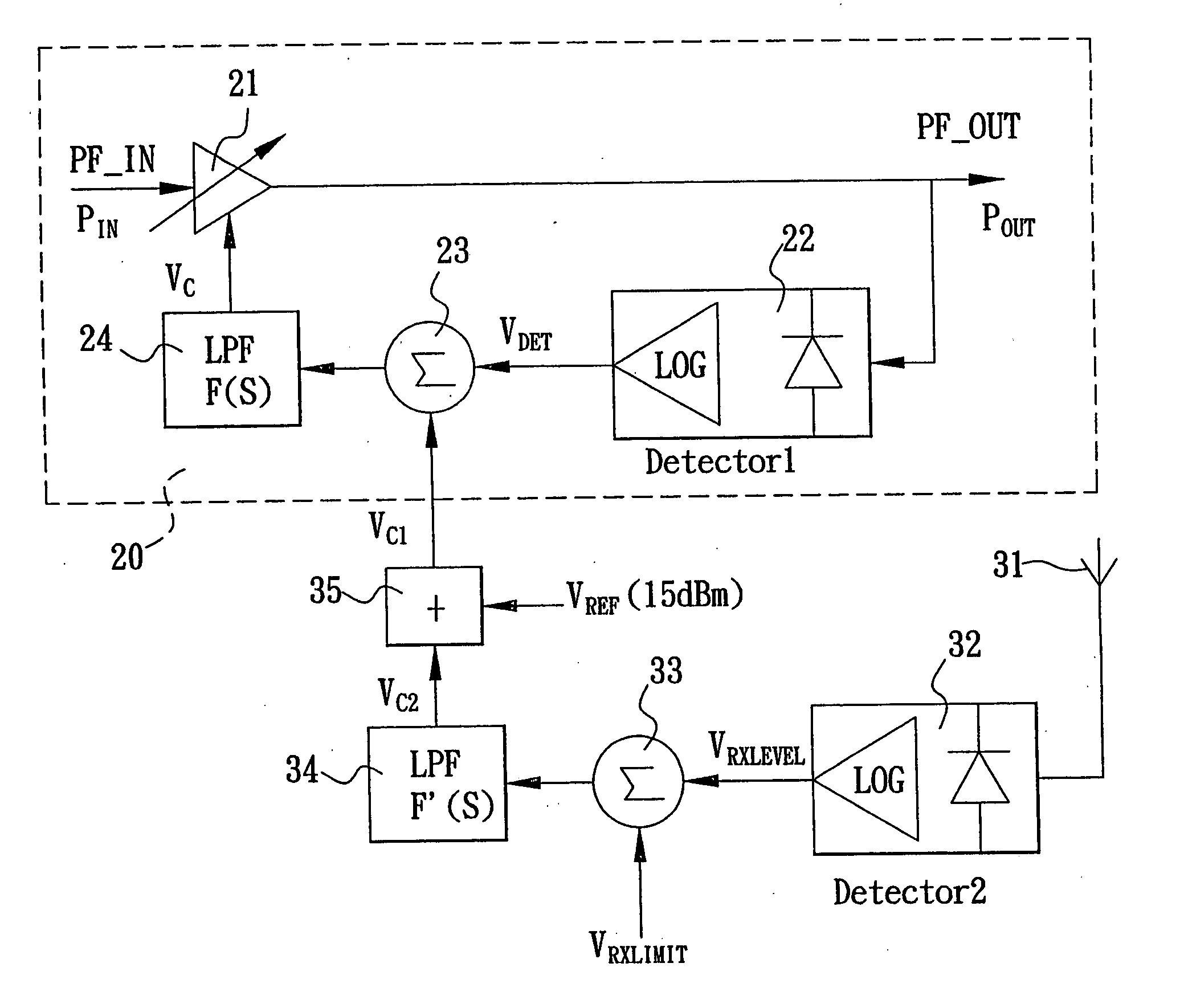
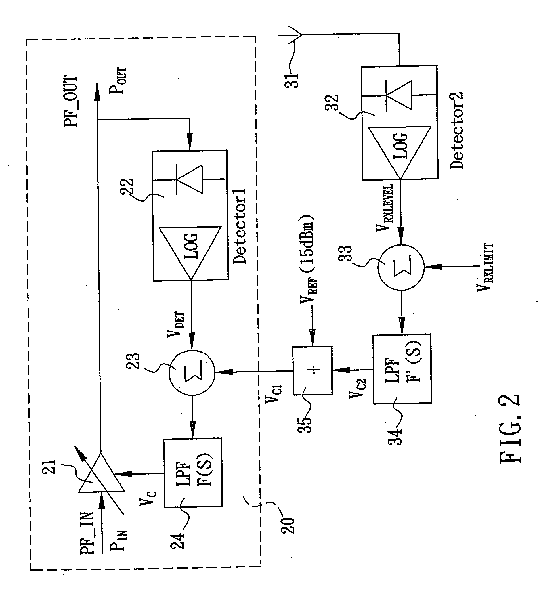
[0014] Referring to FIG. 2, a dynamic power control circuit of a wireless communication device is illustrated. The wireless communication device comprises a radio frequency (RF) auto-gain control circuit 20. The auto-gain control circuit 20 includes a dynamic gain power amplifier 21, a power detector 22, a comparator 23, and a low pass filter 24, wherein another power detector 32, another comparator 33, another low pass filter 34 and an adder 35 are disposed between the comparator 23 and the antenna 31 of the wireless communication device. A reference voltage VREF (15 dBm) is imposed on the adder 35, so as to enable the detector 22 to detect the output power POUT of the amplifier 21. After the detection of the detector 22, an output voltage VDET is generated. The output voltage VDET is further inputted to the comparator 23, and is compared with another reference voltage Vc1 from the adder 35. Later, the filter 24 filters out the noise of the control voltage Vc output from the compar...


PUM


Abstract

The present invention is to provide a dynamic power control circuit for a wireless communication device, which comprises a power detector, a comparator, a low pass filter and an adder disposed between a radio frequency auto-gain control circuit and an antenna thereof. A reference voltage is imposed on the adder to enable the power detector to detect and output signal voltage to the comparator which compares the received voltage with a specified received voltage limit and outputs a reference voltage to the low pass filter for filtering out the noise of the reference voltage and outputting it to the adder. The adder then adds the reference voltage and the specified reference voltage, and outputs the result to the radio frequency auto-gain control circuit for controlling the output power corresponding to the strength of the received signals.

Description

FIELD OF THE INVENTION [0001] The present invention relates generally to a dynamic power control circuit for a wireless communication device, more particularly to an auto-gain control circuit of a wireless communication device which can control output power corresponding to the strength of received signals. When the received signal is weak, the output power is increased, so as to enhance the wireless communication quality. When the received signal is strong, the output power is reduced, so as to decrease power consumption and increase the speaking time on the wireless communication device. BACKGROUND OF THE INVENTION [0002] In recent years, the development of modern technology has forever changed the way people live. In particular, the overwhelming use of wireless communication devices has made the communication between people a much easier task. In addition, a variety of functions, such as game, phone book, voice mail system, calculator, alarm, wireless application protocol (WAP), ...

Claims


Application Information

Patent Timeline
IPC IPC(8): H04B1/04H01Q11/12H03G3/30H04B7/005H04M1/73
CPCH03G3/3042H04W52/52H04W52/245
Inventor HO, DAVIDXIAO, SHENGHUNG, CHIH-CHUNG
Owner INVENTEC APPLIANCES CORP
Why Eureka
Eureka Blog
Learn More