Diversion device to increase cerebral blood flow

Active Publication Date: 2006-03-16
STRYKER EURO OPERATIONS HLDG LLC +1
View PDF39 Cites 94 Cited by
  • Summary
  • Abstract
  • Description
  • Claims
  • Application Information

AI Technical Summary

Benefits of technology

[0007] In one embodiment, the device includes an expandable frame with a membrane mounted on a first portion of the frame. The membrane has at least one opening. In some embodiments, the membrane has an outer region and an inner region, and an opening in the inner region. In use, t

Problems solved by technology

Limitations of this device and method include mechanical complexity, constant monitoring requirements, and maintaining arterial access for the length of its

Method used


Image

  • Diversion device to increase cerebral blood flow
  • Diversion device to increase cerebral blood flow
  • Diversion device to increase cerebral blood flow

Examples


Embodiment Construction

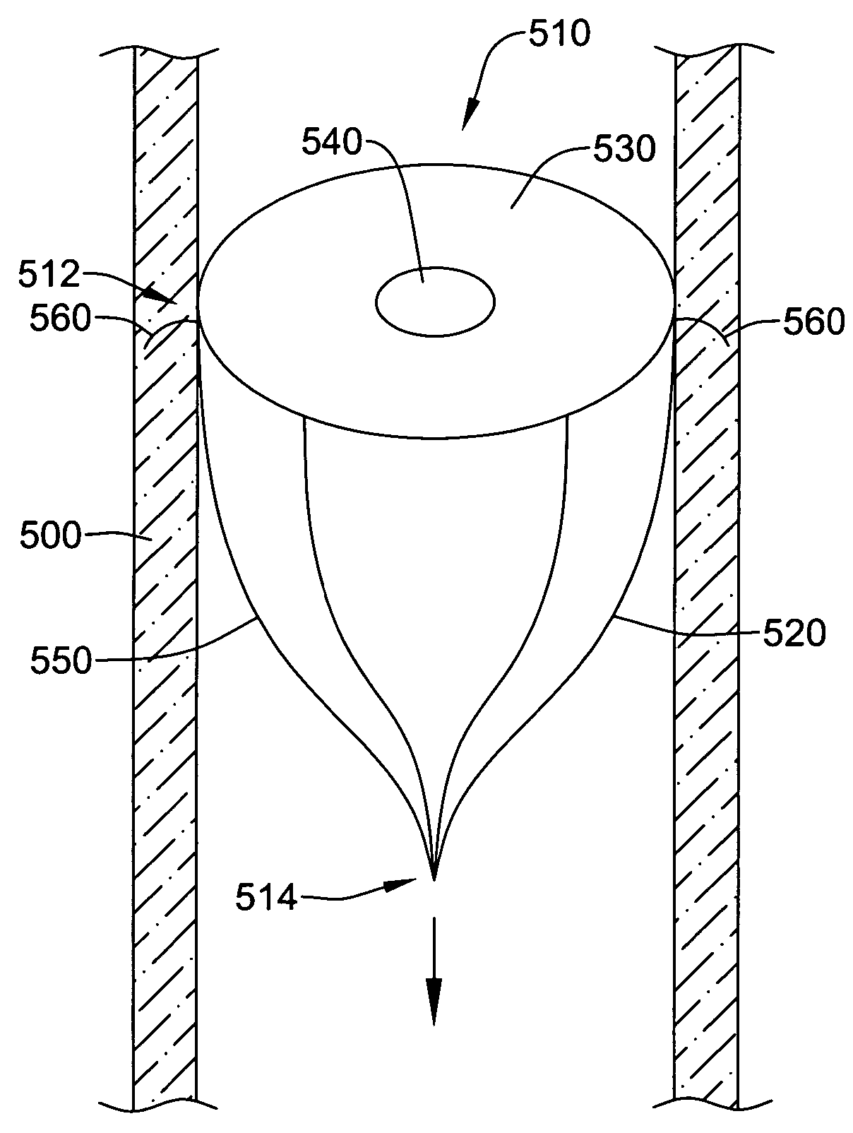
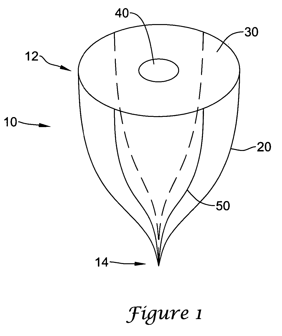
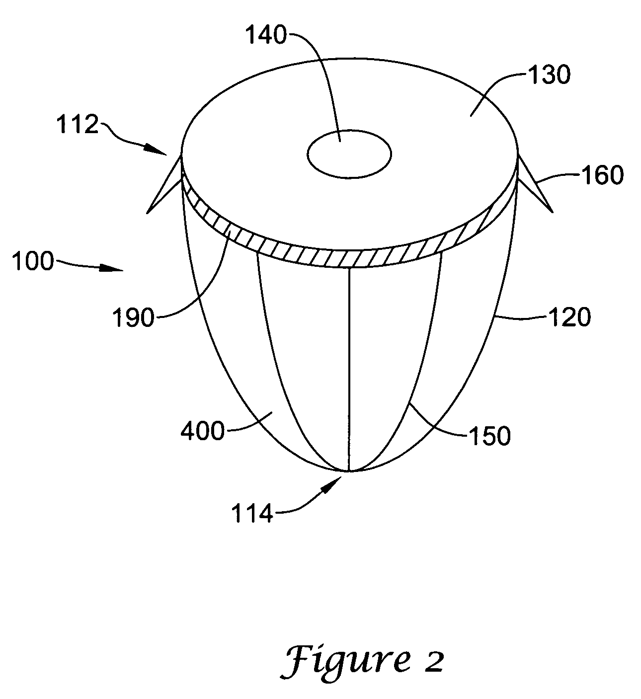
[0014] The filter devices disclosed herein are characterized by their ability to withstand high arterial blood flow rates for an extended time and their ability to expand and contract with the wall of the aorta. In some embodiments, the devices are made of a material that is impermeable to blood such as Teflon or nitinol. The devices can have an anti-thrombogenic coating, such as heparin or Carmeda® BioActive Surface (Carmeda Inc., US). In other embodiments, the devices are made of a material that is permeable to blood, such as a mesh, woven material, or a thin polymer. All or a part of the device can be made of a biodegradable material. The device is collapsible and expandable and can be delivered surgically, endoscopically, or percutaneously with cannulas or intravascular catheters. In one embodiment, the device is introduced through the femoral artery. In another embodiment, the device is introduced through the brachial artery.

[0015] The device can be left in the aorta permanent...


PUM


Abstract

Methods and devices provide for temporary partial aortic occlusion to achieve diversion of blood flow to the brain in patients suffering from cerebral ischemia. The device includes an expandable frame and membrane that is inserted into the aorta to partially occlude blood flow.

Description

FIELD OF THE INVENTION [0001] The present invention relates generally to devices and methods for providing temporary partial obstruction of aortic blood flow, with a resulting increase in cerebral blood flow. More particularly, the invention provides a device with a membrane for partially occluding an artery. BACKGROUND [0002] Stroke is a disruption of blood to a portion of the brain. The two main mechanisms are occlusion of a blood vessel (ischemic stroke) or hemorrhage of a blood vessel (hemorrhagic stroke). Ischemic stroke is significantly more common. Current state of the art treatment for ischemic stroke includes the injection of tissue plasminogen activator (tPA) within four hours of the event. Some evidence also points to a benefit from tPA out to 12 hours. Alternate therapies include mechanical dislocation or retrieval of the clot. These treatments are effective because the brain has significant collateral blood flow. Thus, when the primary blood supply to an area is disrupt...

Claims


Application Information

Patent Timeline
IPC IPC(8): A61M29/00
CPCA61B17/12022A61B17/12036A61B17/12109A61B17/12136A61B17/12172A61B2017/00615A61B2017/00243A61B2017/00575A61B2017/00579A61B2017/00592A61B2017/00597A61B2017/00004
Inventor VANCAMP, DANIELNIELSON, ERIC D.
Owner STRYKER EURO OPERATIONS HLDG LLC
Why Eureka
Try Eureka