Polarizing plate protecting film and its manufacturing method, polarizing plate and liquid crystal display

a technology of polarizing plate and protective film, which is applied in the direction of instruments, other domestic objects, transportation and packaging, etc., can solve the problems of poor black display, inability to disclose a liquid crystal display employing a polarizing plate with an optical compensation film, and contamination of parts, so as to reduce contamination, improve displaying quality, and minimize the effect of ruptur

Inactive Publication Date: 2006-03-23
KONICA MINOLTA OPTO
View PDF7 Cites 33 Cited by
  • Summary
  • Abstract
  • Description
  • Claims
  • Application Information

AI Technical Summary

Benefits of technology

[0015] An object of the invention is to provide a polarizing plate protecting film manufactured without employing solvents according to a melt casting method, which reduces contaminations at the lip of an extruder, and minimizes rupture at a slitting section durin

Problems solved by technology

As a result, the polarizing plate protecting film becomes polyfunctional, which results in reduction of parts.
This display provides good black display observed from a direction normal to the display surface, but shows light leak observed from a direction (hereinafter referred to as an oblique viewing angle direction) inclined from the normal direction, resulting in poor black display.
However, this patent document does not disclose a liquid crystal display employing a polarizing plate with an optical compensation film prepared from a concrete resin nor a liquid crystal display employing a polarizing plate with a polarizing plate protecting film having an optical compensation property for viewing angle

Method used


Image

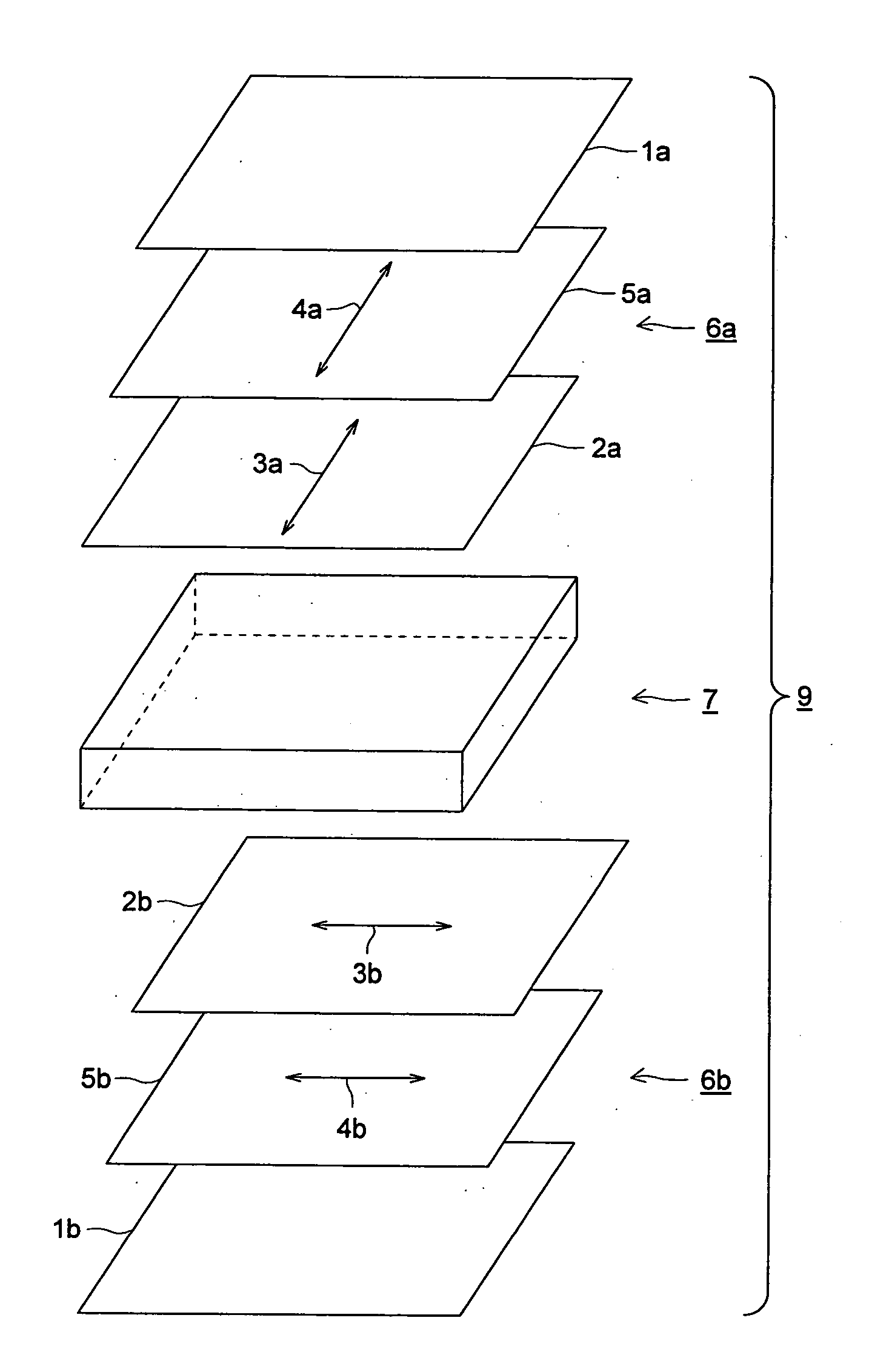
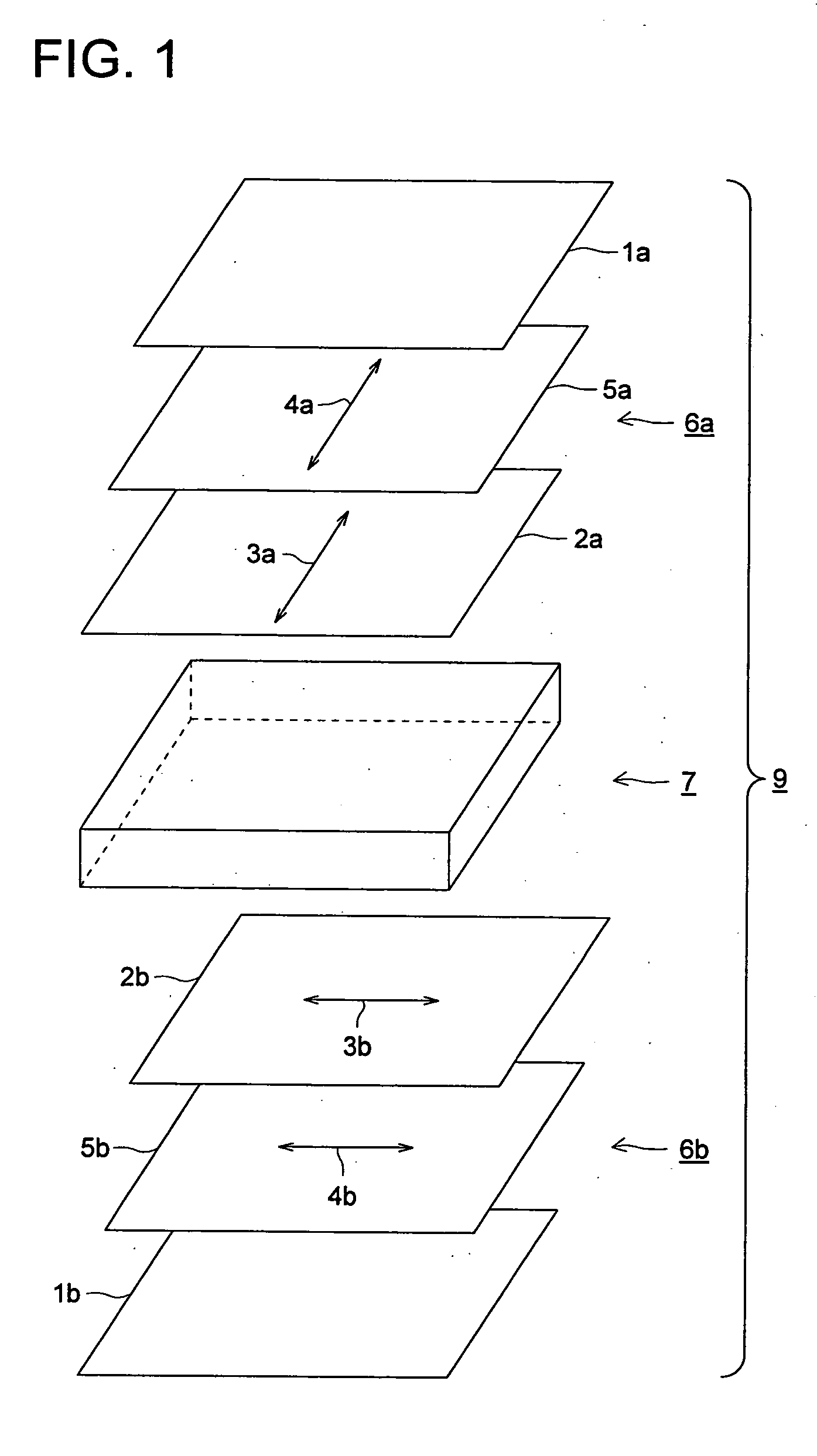
  • Polarizing plate protecting film and its manufacturing method, polarizing plate and liquid crystal display
  • Polarizing plate protecting film and its manufacturing method, polarizing plate and liquid crystal display
  • Polarizing plate protecting film and its manufacturing method, polarizing plate and liquid crystal display

Examples


example 1

(Preparation of Polarizing Plate Protecting Film Samples 1 through 17)

[0196] The above cellulose resin 1 was heat treated at 120° C. for 1 hour and cooled to room temperature in a dried air. The above plasticizer and additives were added in the amount described above to 90 parts by weight of the dried cellulose resin to have a composition as shown in polarizing plate protecting film sample 1 of Table 1. The resulting composition was mixed in a Henschel mixer, heated in an extruder to prepare pellets and cooled.

[0197] The pellets was dried at 120° C., heat melted at a heat melting temperature as shown in Table 1, extruded from a T die employing an extruder to form a web, stretching the web at 158° C., which was obtained from a roller temperature, in the longitudinal direction by a stretching magnification of 1.1, then stretching the web in a tenter in the lateral direction by a stretching magnification of 1.4, and relaxed. Subsequently, both edges of the web being slit at a slitti...


PUM

PropertyMeasurementUnit
Fractionaaaaaaaaaa
Fractionaaaaaaaaaa
Fractionaaaaaaaaaa

Abstract

Disclosed is a process for manufacturing a polarizing plate protecting film comprising the steps of providing a film formation composition containing cellulose resin having a total acyl substitution degree of from 2.5 to 2.9, a plasticizer and a hindered amine or hindered phenol compound, heat-melting the film formation composition to obtain a melt, extruding the melt to be in the form of sheet, and cooling the extruded sheet to form a film, wherein the cellulose resin contains an alkaline earth metal in an amount of from 1 to 50 ppm and a residual sulfuric acid (in terms of sulfur content) in an amount of from 0.1 to 45 ppm, based on the weight of cellulose resin.

Description

[0001] This application is based on Japanese Patent Application No. 2004-271357 filed on Sep. 17, 2004, in Japanese Patent Office, the entire content of which is hereby incorporated by reference. FIELD OF THE INVENTION [0002] The present invention relates to a polarizing plate protecting film and its manufacturing method, a polarizing plate, and a liquid crystal display. BACKGROUND OF THE INVENTION [0003] A polarizing plate protecting film is used for protecting a polarizing film. The polarizing plate protecting film is provided on both sides of the polarizing film to form a polarizing plate. Hitherto, a displaying quality of a liquid crystal display has been improved by an optical compensation film which is a viewing angle compensation film having an optical retardation film. Recently, function of an optical retardation film has been added to a polarizing plate protecting film. As a result, the polarizing plate protecting film becomes polyfunctional, which results in reduction of p...

Claims


Application Information

Patent Timeline
IPC IPC(8): B29C47/88C09K19/00B29C48/08B29C48/305
CPCB29C47/0004Y10T428/105B29C47/0021B29C47/14B29C47/8805B29C47/8845B29C47/885B29K2001/00B29K2001/12B29K2105/0038B29K2105/005B29K2105/256C08J5/18C08J2301/10G02B1/105G02B5/3033Y10T428/1041B29C47/0019B29C48/022B29C48/07B29C48/08B29C48/305B29C48/91B29C48/914B29C48/9145B29C48/9165G02B1/14C09K2323/035C09K2323/031C08B3/06
Inventor MURAKAMI, TAKASHI
Owner KONICA MINOLTA OPTO
Why Eureka
Try Eureka