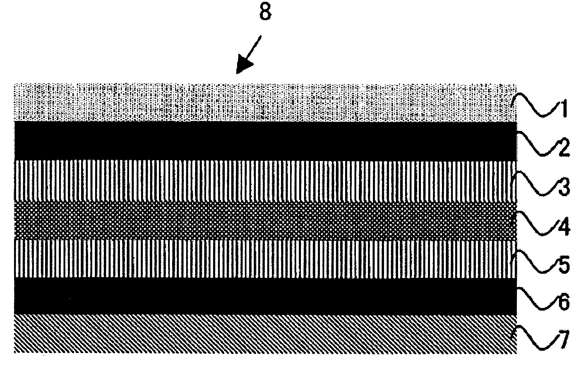
Optical laminate

a technology of optical laminate and glass base material, applied in the field of optical laminate, can solve the problems of peeling between the adhesive layer and the glass base material, light leakage, and tn liquid crystal cell light leakage, and achieve the effect of reducing light leakage and excellent durability

Active Publication Date: 2006-03-23
SUMITOMO CHEM CO LTD
View PDF15 Cites 40 Cited by
  • Summary
  • Abstract
  • Description
  • Claims
  • Application Information

AI Technical Summary

Benefits of technology

[0010] An object of the present invention is to provide an optical laminate having suppressed light leakage and excellent in durability.

Problems solved by technology

Adhesive layers 3 and 5 used in such an optical laminate tend to generate curl and the like due to large dimension change by expansion and shrinkage under heating or moistening and heating conditions, consequently, there are problems such as occurrence of foaming in an adhesive layer of the resulted optical laminate, generation of peeling between an adhesive layer and a glass base material, and the like.
Under heating or moistening and heating conditions, distribution of remaining stress acting on an optical film such as an anti-reflection film 1, polarizing film 2 and the like becomes non-uniform, concentration of stress occurs around peripheral parts of an optical laminate, consequently, there is a problem that light leakage occurs in a TN liquid crystal cell (TFT).
However, when an optical laminate having a constitution of anti-reflection film / polarizing film / adhesive layer / glass base material / adhesive layer / polarizing film is produced using the adhesive on both surfaces of the glass base material and one cycle of 60° C.→−20° C.→60° C. is repeated 100 times, then, peeling, hazing and the like occur on the surface of a glass plate, durability thereof is not sufficient, and light leakage occurs, in some case.

Method used


Image

  • Optical laminate
  • Optical laminate
  • Optical laminate

Examples


example 2

Polymerization Example 2

[0144] A reaction vessel equipped with a cooling tube, nitrogen introduction tube, thermometer and stirrer was charged 100 parts of ethyl acetate, 98.9 parts of butyl acrylate as a monomer (a) and 1.1 parts of acrylic acid as a polar functional group-containing monomer, air in the apparatus was purged with a nitrogen gas, and the inner temperature was raised to 70° C. while maintaining no oxygen-containing atmosphere, then, a solution prepared by dissolving 0.03 parts of azobisisobutyronitrile (hereinafter, referred to as AIBN) in 10 parts of ethyl acetate was added in its entirety. Thereafter, the inner temperature was kept at 69 to 71° C. for 12 hours, to complete the reaction. The weight-average molecular weight based on polystyrene calibration standard of GPC was 1,200,000, and Mw / Mn was 3.9.

example 1

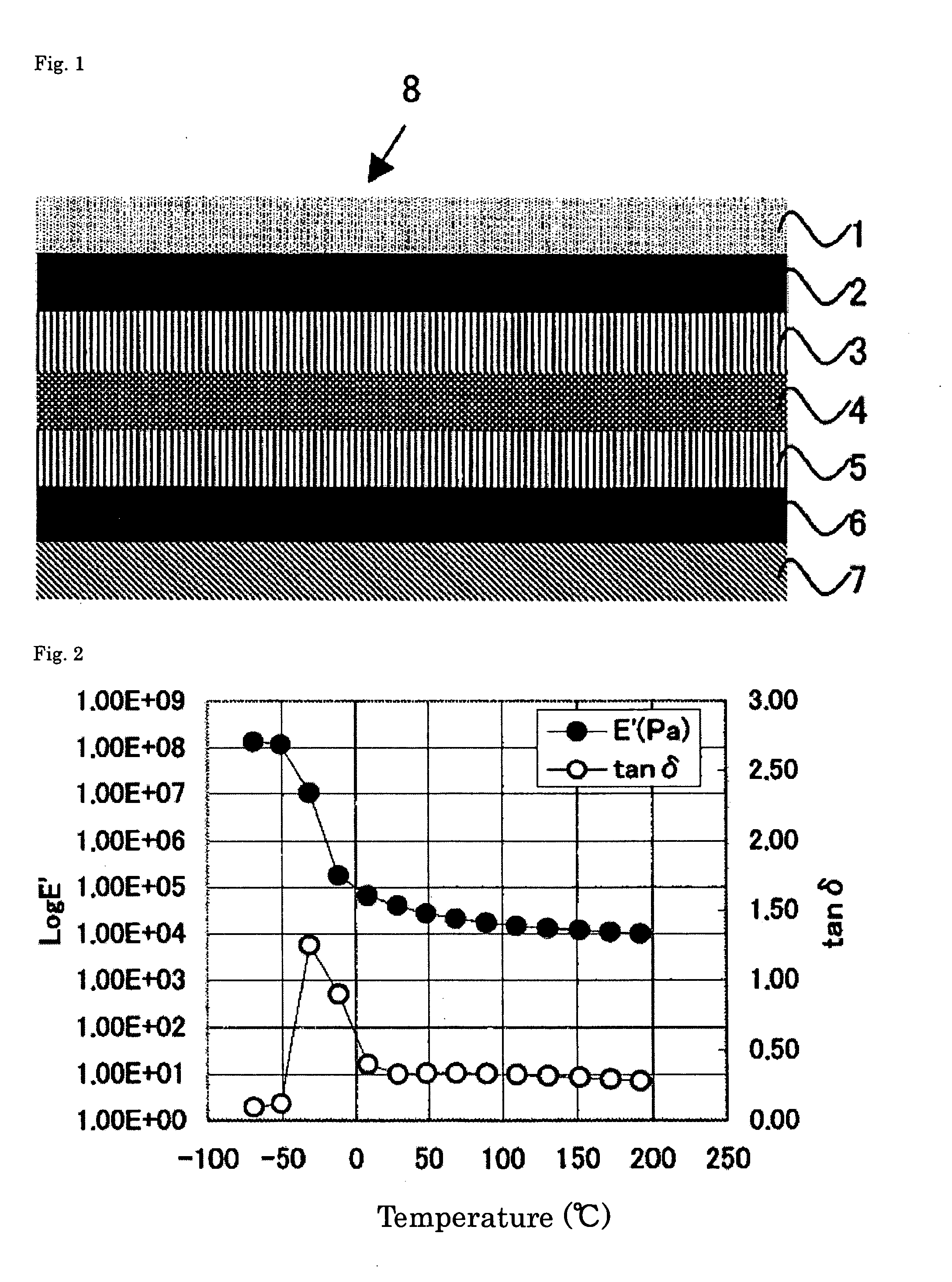
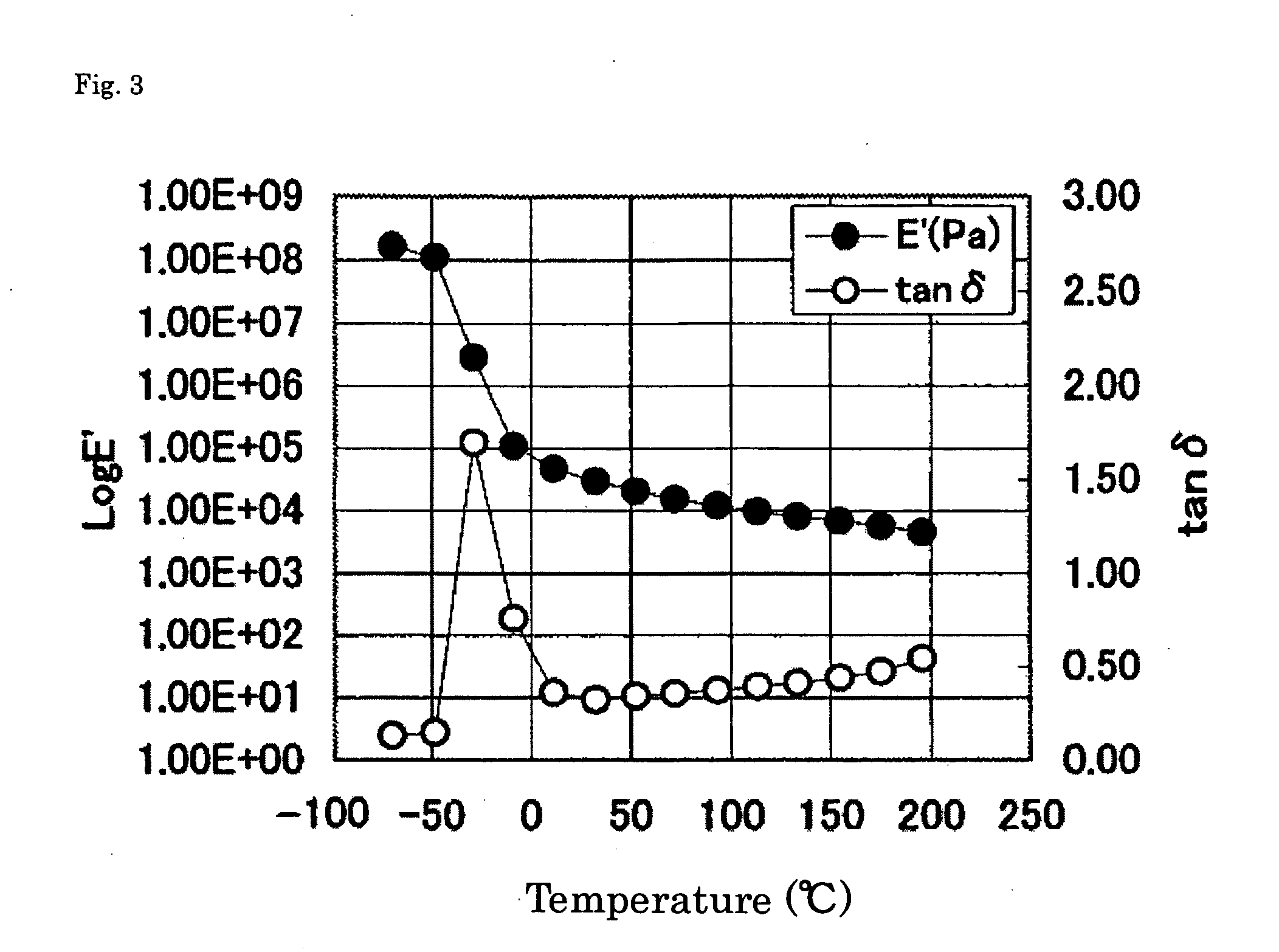
[0145] Acrylic resins (1) and (2) were mixed in a weight ratio shown in Table 1, to obtain an ethyl acetate solution of an acrylic resin composition. 100 parts of solid components in the resulting solution were mixed with 0.07 parts (solid content) of a cross-linking agent, polyisocyanate-based compound (trade name: Takenate D-110 N, manufactured by Mitsui Takeda Chemical) and 0.1 part (solid content) of a silane compound (trade name: Y11597, manufactured by Nippon Unicar), to obtain an adhesive (1) of the present invention. In the same manner, an adhesive (2) was prepared. The mixing ratio of the acrylic resins (1) and (2), cross-linking agent, silane-based compound and loss tangent are shown in Table 1.

TABLE 1cross-linking agentacrylic resin (1)acrylic resin (2)(isocyanatesilane-storagenon-non-compound)based compoundmodulusmaximumpolymeri-volatilepolymeri-volatileuseusepeakat peakvaluezationcontentzationcontentamountamounttempera-tempera-lossexample(parts)example(parts)kind(part...


PUM

PropertyMeasurementUnit
frequencyaaaaaaaaaa
temperatureaaaaaaaaaa
viscosityaaaaaaaaaa

Abstract

An optical laminate comprising an anti-reflection film 1, polarizing film 2, adhesive layer 3, glass cell for liquid crystal display 4, adhesive layer 5 and polarizing film 6 laminated sequentially, wherein the ratio (A/B) of the maximum value A of the loss tangent of the adhesive layer 3 to the maximum value B of the loss tangent of the adhesive layer 5 is 1.1 or more. The maximum value of the loss tangent means the maximum value of loss modulus (E″)/storage modulus (E′) (=tan δ), each measured by heating the adhesive layer in a temperature range of −70° C. to 200° C. at a temperature rising rate of 4° C./min and a frequency of 1 Hz.

Description

BACKGROUND OF THE INVENTION [0001] 1. Technical Field of the Invention [0002] The present invention relates to an optical laminate. [0003] 2. Description of the Related Art [0004] Liquid crystal cells generally used in liquid crystal displays such as a TN liquid crystal cell (TFT), a STN liquid crystal cell (STN) and the like, have a structure in which a liquid crystal component is sandwiched between two glass base materials. On the surface of the glass base material, an optical film such as a polarizing film, phase retardation film and the like is laminated via an adhesive composed mainly of an acrylic resin. [0005] An optical laminate composed of an anti-reflection film 1, polarizing film 2, adhesive layer 3, glass cell for liquid crystal display 4, adhesive layer 5 and polarizing film 6 laminated in this order is in general used. [0006] Adhesive layers 3 and 5 used in such an optical laminate tend to generate curl and the like due to large dimension change by expansion and shrink...

Claims


Application Information

Patent Timeline
Patent Type & Authority Applications(United States)
IPC IPC(8): B32B37/00C09K19/00
CPCB32B27/00B32B37/12B32B2307/42B32B2457/20Y10T428/1059G02F2202/28Y10T428/1036Y10T156/10Y10T428/1082G02F1/133502C09K2323/059C09K2323/05C09K2323/03G02F1/1335
Inventor TAKEKO, RYUKAWAMURA, AKIRAHIGO, ATSUSHI
Owner SUMITOMO CHEM CO LTD
Why Eureka
Try Eureka