Recently, a rolling bearing of an auxiliary component part, such as an
alternator of an automotive
internal combustion engine, an
air conditioning unit and an idler
pulley or the like, has heretofore been used under severe conditions like vibrations and temperatures, eliciting the occurrence of flaking accompanied by changes in structures in a new mode.
Further, there are different results due to a difference in a belt span even with the
pulley having the same
diameter, a difference in a
momentum of
inertia of the pulley and a difference in material of a V-ribbed belt and, hence, there are things that cannot be explained in the thinking of the related art.)
Thus, although the brittle flaking of the rolling bearing can be reproduced on the recurrence test in the same face (structure) as the white-banded structure occurred on the actual
machine (automobile), no mechanism is clarified and, hence, different results appear upon presence of conditions under an inconvenient condition.
This also results in a vicious circle in which no generation mechanism is clarified.
It seems to be a current condition that even if a preliminary study is made, the
countermeasure is based on a woefully inadequate scientific basis that seems to be know-how.
Although this issue has begun to occur in the first place when the V-ribbed belt is adopted in earnest (back in the 1980) (with no occurrence of such an issue in the age of a V-belt), no prospect of specifying the causes has yet emerged and, hence, no
counter measures have been established under a current condition.
However, since the structure supplied with the extreme pressure additives has a low incidence of brittle flaking, bearings provided by respective manufacturing companies employ
grease with extreme pressure additives and, even in such a case, no success is attained in precluding the occurrence of the flaking on the ball under current status.
It is a theory that resulting
hydrogen takes positive ions and enters an inside of the outer ring that is negatively charged to cause a change in microstructures to form white bands with the
resultant occurrence of flaking in the final stage.
(Further, although the ball is also negatively charged at a contact area with the inner rind, the ball is also positively charged at the contact area with the outer ring to cause the positive charges and negative charges to alternately appear on the ball with no capability of drawing
hydrogen whereby no flaking takes place.)
However, such thinking is basically strange.
As for another way of thinking, although it is considered that the body of the vehicle is electrically insulated from the ground by means of tires and, so, the outer ring can be negatively charged, this thinking means that it is hardly possible for the ball to encounter the flaking as set forth above and, in
actual practice, a probability occurs wherein only the ball is flaked.
Further, suppose
hydrogen brittleness independently occur with no aid (enhancement) of
static electricity, it completely becomes hard to explain that the
brittleness occurred after the use of the V-ribbed belt and that since hydrogen must be absorbed by both of the contact areas, the flakings concentrate only on the outer ring (under circumstances where
grease with extreme pressure additives is employed, the flakings concentrate on the ball).
However, it is needless to say that such replacement is a completely meaningless
countermeasure (though even if the confirmation is made upon conducting tests, it may be possible that even if lubricating conditions are altered with the
resultant change in flaking recurrence conditions, the cause of the brittle flaking is misguided to be a result of the counter measure without knowing a change in the brittle flaking recurrence conditions).
In addition, as a result of research conducted by the present inventors on a large number of flaked products, no assured basis, in which hydrogen increases, has necessarily been obtained.
Thus, the hydrogen theory had a result to be denied in experimental aspects.
From this, it is concluded that the hydrogen theory is not completely consistent in a reality.
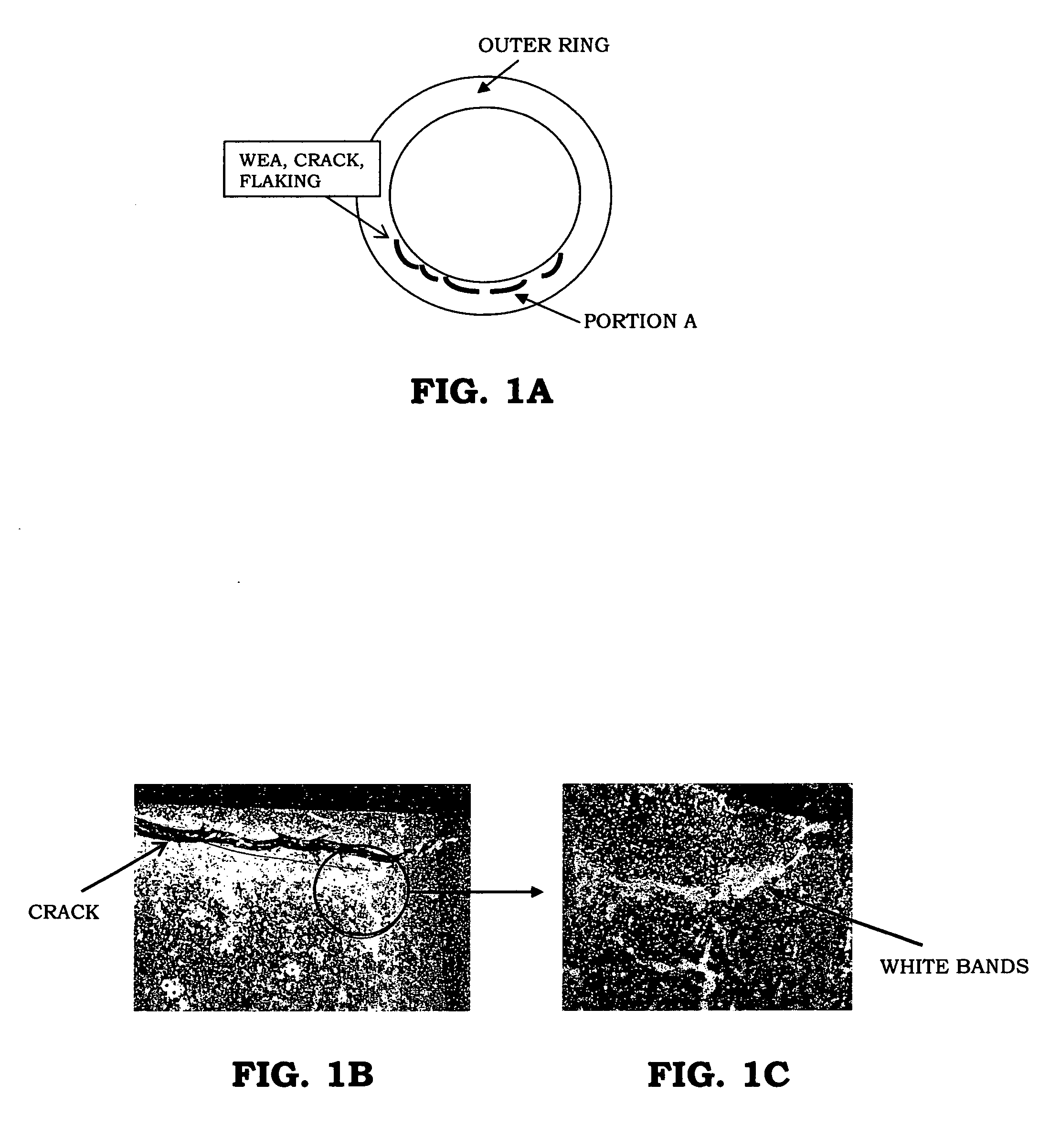
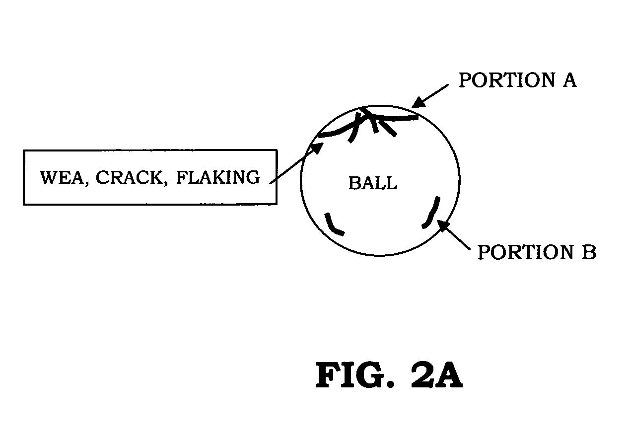
Additionally, this theory does not explain the micro and
macro faces (see FIGS. 1A to 1C, 2A to 2D and FIG. 3) that are the maximum features of the brittle flaking even if this theory comes from a story in that after hydrogen enters (in primary cause), this influence causes the WEA to occur as a secondary failure.
That is, even the primary or secondary failure is hard to answer questions described below.
Thus, in addition to the presence of the experimental basis that is grossly questionable, the hydrogen theory is hard to explain the
macro and micro faces involving the WEA.
Thereafter, this portion encounters cracks due to a difference in the white bands and the matrix structure to result in the flaking.
However, this theory is hard to explain that although the pressure (so-called
Hertz's
contact pressure) on the contact area between an inner race and the ball acts on both component elements and the resulting internal stresses are equal to each other, while these components are made of same material, the brittle flaking must occur in the inner ring and the ball at substantially the same rate but the inner ring is not damaged whereas the flaking has occurred only in the ball (likewise, it is hard to explain that the flaking occurs only in the outer ring with the use of
grease with no inclusion of additives).
Additionally, when calculating with a
numeric value as a result of actual experiments, no matching is obtained in a quantitative sense.
That is, the above-described value represents an unrealistic value in that the bearing enters the plastic deformation region or a phase wherein the bearing is completely damaged with no profile of the ball being maintained.
In addition, although attempts have heretofore been undertaken to address a discrepancy based on a compound condition associated with the
Hertz's stress in consideration of the influence of a
residual stress in an internal part of material, taking a compound stress causes the stress to have a further shallow peak (this means that the compound is shallower than that of the
Hertz's theory by itself in terms of the same load, but the other side of the
coin is that there is a further increase in the load equivalent to a deep position of the WEA in the experimental tests), resulting in the occurrence of further extraordinary
shear stress and load.
That is, the Hertz's theory is impossible to be quantitatively explained.
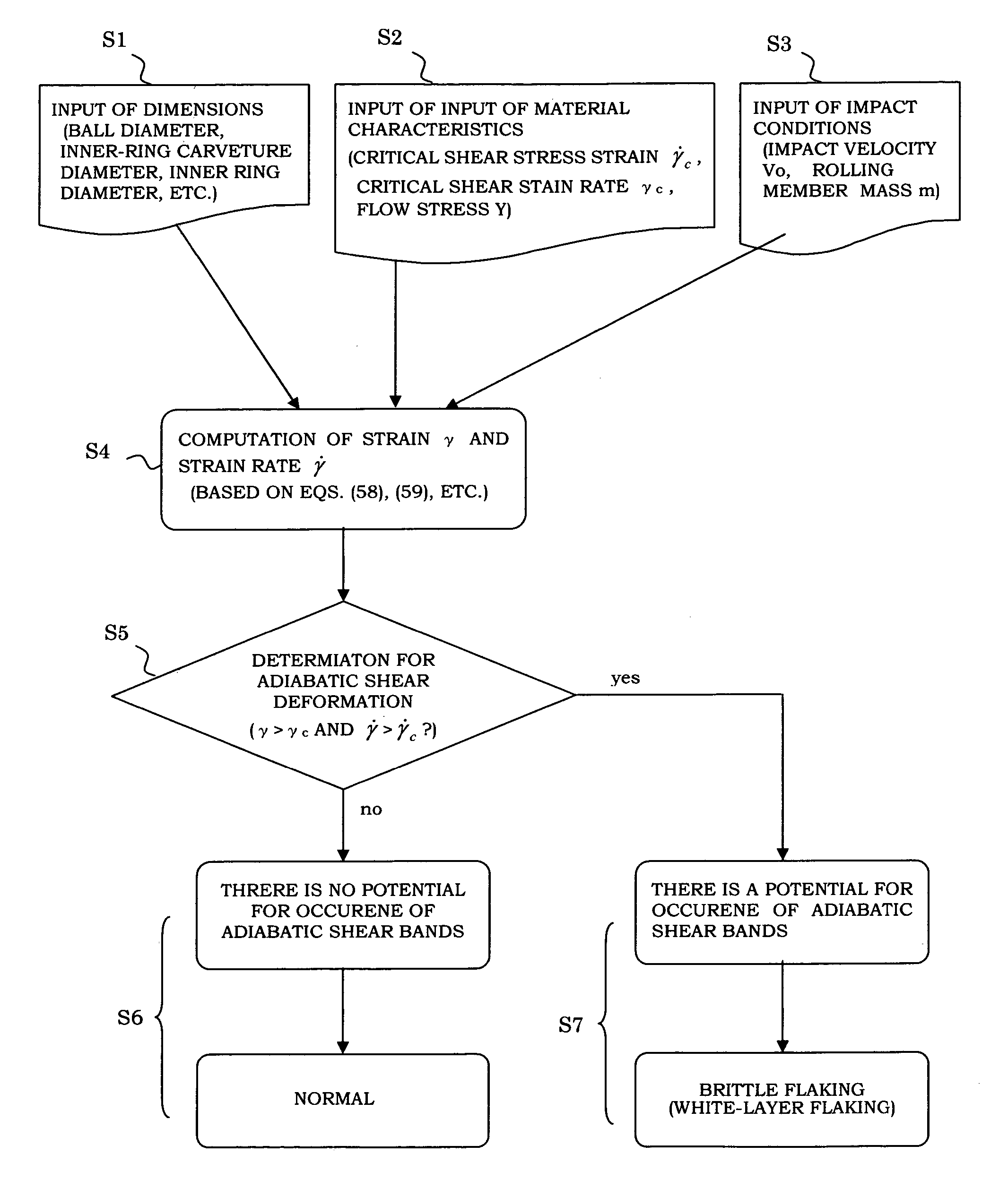
In other words, a behavior is determined to be general fatigue life or to be brittle flaking depending on data and erroneous use of data results in a danger of misleading judgment.
Stated another way, the presence of breakdown forms determined with
uncertain data is convenient for explaining the result of breakdown (in an excuse for saying that the fatigue life occurred because of cursory data such as for instance information in that the first term wins), but such an attempt is inconvenient for predicting the breakdown form in advance.
Consequently, this theory is impossible to provide a target value and a threshold value for the design to be made.
As set forth above, since the doctrine for the general fatigue life is already established and the two mechanisms do not meet an actual condition in terms of the brittle flaking regardless of the presence of a possibility in life prediction, a situation remains in a condition under which it is completely hard to understand which
stress factor of an actual
machine influences in what way.
Accordingly, the situation is that of course, the life prediction on design cannot be made nor
countermeasure cannot be made.
Further, in recent years, although with a view to achieving a small size and lightweight configuration, a
belt drive system of a serpentine
system, in which a large number of pulleys are driven with a single belt, has been incorporated in an engine, an issue arises with an increase in a tension,
resonance in belt and engine vibration and under such situations, stresses applied to the bearing become complex.
A situation holds that no countermeasure can be undertaken for such an issue.
Despite the bearing forms an important mechanical component part, not only life prediction cannot be made for the brittle flaking of the rolling bearing but also even a mechanism cannot be established.
As mentioned above, despite the brittle flaking has an extremely
short life as compared to the usual fatigue life (in an actual
alternator, no chance has occurred in the past for the fatigue life to become a problem), a mechanism, which can explain such a phenomenon, is not established and remains under a condition wherein no appropriate countermeasure is undertaken.
Since there is no choice, the current status holds in an ineffective way that discrete countermeasures are undertaken for auxiliary devices of the engine, respectively, and confirmations are made by conducting tests on actual machines.
Therefore, it is a current condition that the bearing is unnecessarily increased in size or a precision is increased in waste in labor and even such countermeasures are not effective to fully overcome the deficiencies.

