System and sub-systems for production and use of hydrogen

a technology of hydrogen fuel and system, applied in the field of hydrogen production, can solve the problems of increasing capital costs, hydrogen fuel cost (at least $15 per kilogram of hydrogen), and the inability to produce hydrogen as cheaply as the steam reforming of methane, and achieve the effect of maximising the stack efficiency

Inactive Publication Date: 2006-03-30
GM GLOBAL TECH OPERATIONS LLC
View PDF19 Cites 62 Cited by
  • Summary
  • Abstract
  • Description
  • Claims
  • Application Information

AI Technical Summary

Benefits of technology

[0008] In one embodiment of the invention, the system is formed of at least one photovoltaic (“PV”) module having at least one PV cell supplying power to electrolyze water, and an electrolyzer receiving the power. The electrolyzer has at least one MEA. The system is optimized in a first mode, which has a PV subsystem designed to give the optimum voltage (that operating voltage which gives the maximum solar energy to hydrogen conversion efficiency) for the electrolyzer. In the first mode, the PV subsystem is directly connected to the electrolyzer subsystem. The system is further operable in a second mode by stepping-down the voltage of a non-optimum PV system to the optimum voltage when the voltage of the PV module exceeds the voltage target of the electrolyzer. The system is further operable in a third mode by stepping-up the voltage when the voltage of the PV module is less than the operating voltage of the electrolyzer. In the second and third modes, the PV voltage is stepped by adding DC-DC converters to the circuit.
[0009] A PV-electrolyzer can be built to operate at maximum efficiency in the first mode with a PV system directly connected to an electrolyzer. An optional con

Problems solved by technology

However, systems consisting of solar cells in PV modules to make electricity together with electrolyzers to dissociate water into hydrogen and oxygen, as they exist today, cannot produce hydrogen as cheaply as the steam reforming of methane.
These projects proved unsatisfactory due to the low efficiency and high cost of the combined technology, which only converted about 2%-6% of the solar energy to hydrogen fuel energy, thus, greatly increasing capital c

Method used


Image

  • System and sub-systems for production and use of hydrogen
  • System and sub-systems for production and use of hydrogen
  • System and sub-systems for production and use of hydrogen

Examples


Embodiment Construction

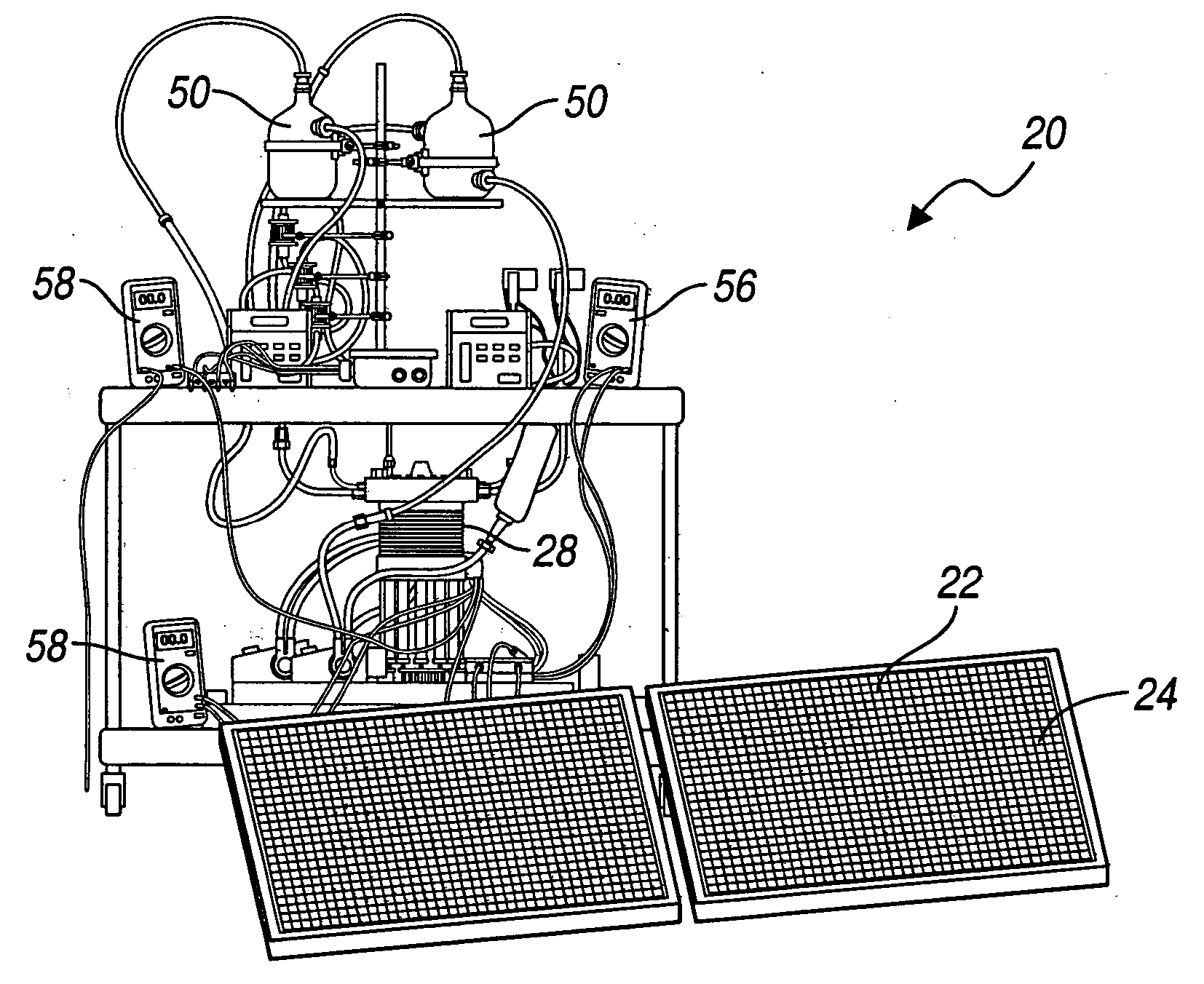
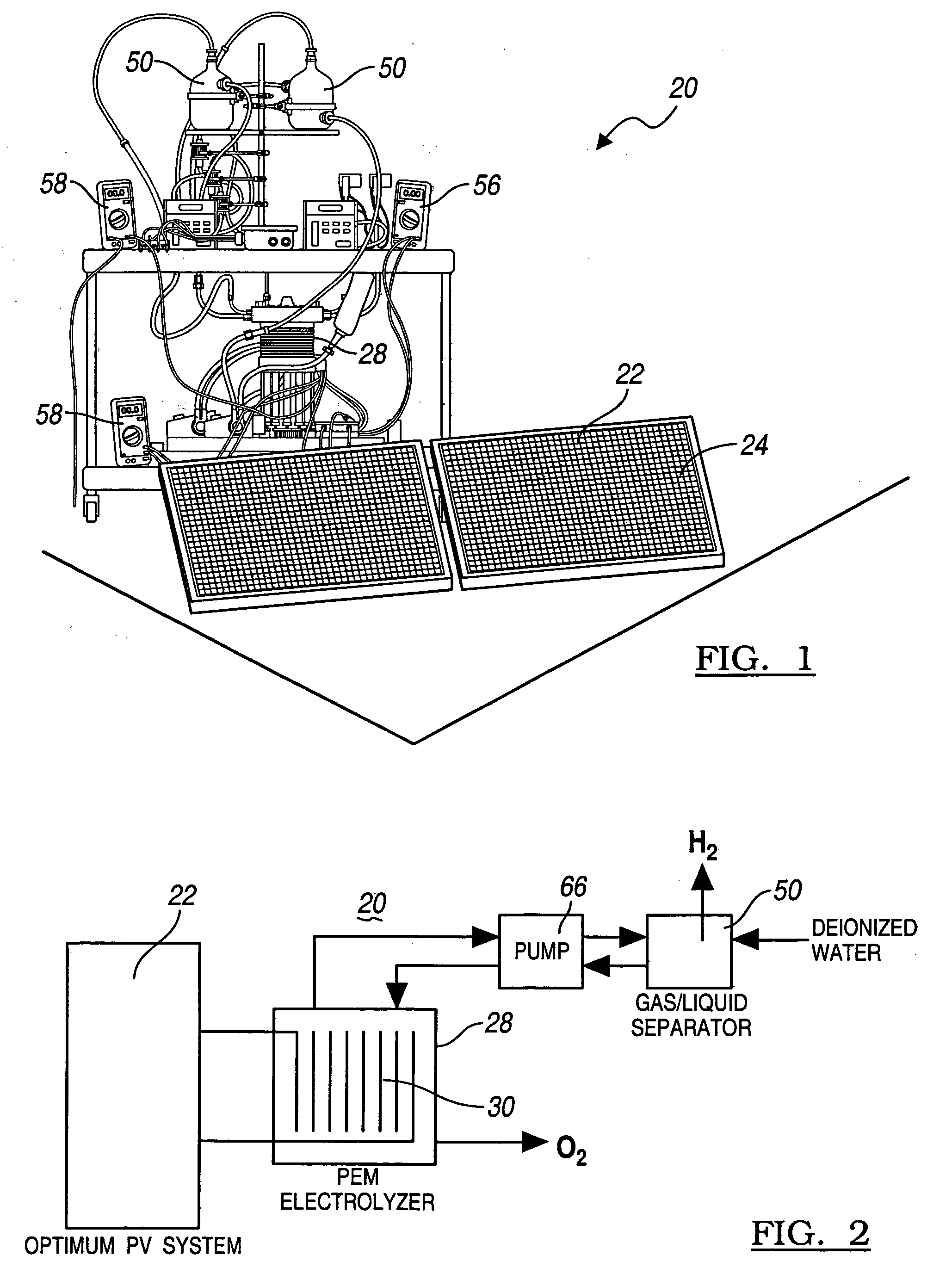
[0027] Operation of the PV-electrolyzer system is explained with general reference to FIGS. 1 and 2, which represent a diagram and schematic of the system according to the teachings of the present invention. The PV-electrolyzer system 20 has a photovoltaic (PV) subsystem 22 having at least one solar or PV cell 24 or PV subsystem 22 and an electrolyzer subsystem 28 having at least one electrolysis cell or membrane electrode assembly (MEA) 30 for electrolyzing water to generate hydrogen. The electrolysis cell 30 is preferably a high efficiency Proton Exchange Membrane (PEM) sandwiched between two catalyzed electrodes to form a membrane electrode assembly (MEA). The voltage and current requirements of the electrolyzer subsystem 28 are matched with the voltage of the electricity produced by the solar powered photovoltaic (“PV”) subsystem 22 to significantly increase the operating efficiency of the overall system 20. As described below in detail, the system 20 optionally utilizes a high ...


PUM

PropertyMeasurementUnit
Pressureaaaaaaaaaa
Pressureaaaaaaaaaa
Electric potential / voltageaaaaaaaaaa

Abstract

A method for optimizing the efficiency of a solar powered hydrogen generation system is disclosed. The system utilizes photovoltaic modules and a proton exchange membrane electrolyzer to split water into hydrogen and oxygen with an efficiency greater than 12%. This high efficiency for the solar powered electrolysis of water was obtained by matching the voltage generated by photovoltaic modules to the operating voltage of the electrolyzer. Optimizing PV-electrolysis systems makes solar generated hydrogen less expensive and more practical for use as an environmentally clean and renewable fuel.

Description

CROSS-REFERENCE TO RELATED APPLICATIONS [0001] This application claims the benefit of U.S. Provisional Application No. 60 / 581,077, filed on Jun. 18, 2004 and application U.S. Ser. No. 11 / 049,213, filed on Feb. 2, 2005, entitled “Method and Apparatus for Hydrogen Generation” which claims priority to U.S. Provisional Application 60 / 545,379, filed on Feb. 18, 2004. The disclosure of the above applications is incorporated herein by reference.FIELD OF THE INVENTION [0002] The present invention generally relates to hydrogen production and, more particularly, to a system and method of producing hydrogen utilizing photovoltaic cells to power a membrane electrode assembly to electrolyze water to form hydrogen. BACKGROUND OF THE INVENTION [0003] Currently the major process by which hydrogen is produced is by the steam reforming of methane. Another means of making hydrogen is by the electrolysis of water. The electricity required for electrolysis is mainly derived from the electric power grid,...

Claims


Application Information

Patent Timeline
IPC IPC(8): H01L25/00H02N6/00
CPCC25B1/04C25B1/12C25B15/00C25B15/02H01L31/042Y02E70/10H01M2008/1095Y02E10/50Y02E60/321Y02E60/366Y02E60/528H01M8/186H01L31/02021H02S10/20Y02E60/32Y02E60/50Y02E60/36Y02P20/133Y02E70/30C25B9/05C25B9/40
Inventor GIBSON, THOMAS L.KELLY, NELSON A.
Owner GM GLOBAL TECH OPERATIONS LLC
Why Eureka
Try Eureka