Color filter and liquid crystal display device using it, and their manufacturing methods

Inactive Publication Date: 2006-04-06
TPO HONG KONG HLDG
View PDF8 Cites 4 Cited by
  • Summary
  • Abstract
  • Description
  • Claims
  • Application Information

AI Technical Summary

Benefits of technology

[0029] In this way, it is possible to manufacture a liquid crystal display device which can fully make the most of the advantages of the above-described color filter.
[0030] This aspect may further comprise a pixel electrode forming step of forming the transmissive and reflective electrode parts in substantially the same heights. This liberates the system from a complicated

Problems solved by technology

This results in deterioration in quality of displayed colors over the display area.
However, the structure forming such a dual cell gap within a pixel is subject to many constraints of other elements such as a TFT forming layer, which is disadvantageous in terms of manufacturing.
Furthermore, since the conductor of the reflective electrode part extends to and couples with the end of the transmissive electrode part which is sma

Method used


Image

  • Color filter and liquid crystal display device using it, and their manufacturing methods
  • Color filter and liquid crystal display device using it, and their manufacturing methods
  • Color filter and liquid crystal display device using it, and their manufacturing methods

Examples


Example

Embodiment 1

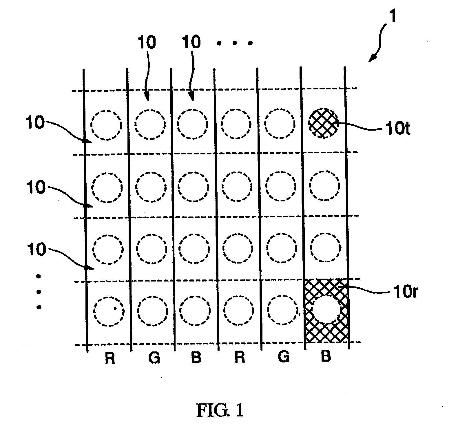
[0039]FIG. 1 shows in schematic plan view a color filter 1 used in a liquid crystal display device according to a first embodiment of the present invention.

[0040] This color filter 1 is partitioned longitudinal coloring areas each extending in the vertical direction of a display screen and having one of red (R), green (G) and blue (B) coloring matters. These longitudinal coloring areas are cyclically arranged in the horizontal direction of the display screen in order of R, G and B. One longitudinal coloring area can be further divided in the vertical direction, and each of the divisional portions corresponds to one pixel. Hereinafter, this divisional portion will be referred to as a “pixel area portion 10.” It is noted that althiugh the longitudinal coloring areas are divided in the vertical direction by dotted lines in FIG. 1, the pixel area portions 10 in one longitudinal coloring area (pixel area portions 10 arranged in the vertical direction) are neither isolated m...

Example

Embodiment 2

[0068] A further improved version of the above-described embodiment will be shown in FIG. 3 as a second embodiment.

[0069] A pixel area portion 10A of a color filter 1A in FIG. 3 comprises a layer 30A as a step-forming layer including an optically transmissive base material (or matrix material) 3S and many optically transmissive particles 3P which have a refractive index different from that of this base material and are scatteringly mixed thereinto. The rest of the configuration is the same as that in FIG. 2.

[0070] The step-forming layer 30A has an effect of diffusing (or scattering) light entering and passing through this layer. Such a diffusing effect is mainly caused by the difference in the refractive index between the base material 3S and particles 3P, but it also depends on parameters such as the shape and size of the particles, density of the particles in the base material or distribution state of the particles in the base material. To prevent coloring caused by...


PUM


Abstract

An object of the invention is to acquire uniform color purity within a pixel to make a good color reproduction and to easily manufacture it with few constraints. A color filter for coloring a first light ray L1 having a unidirectional optical path and a second light ray L2 having a bidirectional optical path for each pixel (10). The color filter comprises: a first coloring portion 10t for coloring the first light ray L1 and a second coloring portion L2 for coloring the second light ray L2, the first coloring portion 10t having a greater thickness than the second coloring portion 10r, the first coloring portion 10t being formed in subsidence with respect to the second coloring portion 10r with a principal plane of the first coloring portion 10t being different in height from a principal plane of the second coloring portion 10r by a predetermined value D.

Description

BACKGROUND OF THE INVENTION [0001] 1. Field of the Invention [0002] The present invention relates to a color filter. The invention also relates to a liquid crystal display device using the color filter. [0003] The present invention especially relates to a color filter handling a first light ray and a second light ray. The first light ray forms a unidirectional optical path in which incident light from one principal plane side of the color filter is transmitted through the filter only once to be colored and is led to the other principal plane side. The second light ray forms a bidirectional optical path in which incident light from the other principal plane side of the color filter is transmitted through the filter to be colored, and the transmitted light is reflected by a light reflective element or the like disposed on the one principal plane side to enter the filter again, transmitted through the filter to be colored and returned to the other principal plane side. The invention al...

Claims


Application Information

Patent Timeline
IPC IPC(8): G02F1/1335G02B5/20
CPCG02F1/133514G02F1/133555G02F1/133516G02F1/1335
Inventor UKAWA, YUSEI
Owner TPO HONG KONG HLDG
Why Eureka
Try Eureka