Supercharge Your Innovation With Domain-Expert AI Agents!

Method for characterization of the illuminator in a lithographic system

a technology of lithographic system and illumination, applied in the field of characterizing lithographic projection equipment, can solve the problems of non-uniformity and non-ideal illumination pattern, non-ideal behavior in the imaging performance of an exposure system, and possible variations of other non-uniformities

Inactive Publication Date: 2006-04-06
CADENCE DESIGN SYST INC
View PDF5 Cites 8 Cited by
  • Summary
  • Abstract
  • Description
  • Claims
  • Application Information

AI Technical Summary

Benefits of technology

The present invention provides methods for measuring the intensity distribution of an illuminator in a lithographic system. These methods use a test mask and a photoresist detector that includes a positive photoresist film deposited on a wafer. The methods involve exposing the detector to a bright feature of the test mask and analyzing the resulting exposure pattern to determine the characteristics of the illuminator. The methods can be used to modify the layout of the exposure field based on the pupil information of the illuminator.

Problems solved by technology

A common cause of such variations is nonuniform temperature distributions across the post exposure bake plate.
Given these distributions it is now apparent that a variety of other non-uniformities and non ideal illumination patterns are possible.
Such imperfections lead to variations and non ideal behavior in the imaging performance of an exposure system.

Method used


Image

  • Method for characterization of the illuminator in a lithographic system
  • Method for characterization of the illuminator in a lithographic system
  • Method for characterization of the illuminator in a lithographic system

Examples


Embodiment Construction

Characterization of the Illuminator Using a Double Exposure Technique

[0029] Referring to FIG. 6A, a test structure that may be used to characterize the intensity distribution of an illuminator by a double exposure method embodying the present invention comprises mask 10 that defines a large transparent window 11 and a smaller transparent opening 12 in an opaque field. Mask 10 is typically made by depositing a thin film of chromium on a fused silica plate and then etching the chromium to define window 11 and opening 12.

[0030] In a preferred implementation of the invention, the opening 12 is round and is more than one micrometer in diameter. The lower limit on the size of the opening is chosen such as to minimize diffraction effects. Smaller openings (in particular when comparable to the wavelength of the light used to image the opening) are less desirable as they are subject to diffraction effects and these complicate the analysis.

[0031] Referring to FIG. 5, two types of exposure...


PUM


Abstract

Pupil intensity distribution of an imaging system is measured by exposing an image field of a radiation detector with a bright feature, positioning the detector at a distance away from the image plane, and exposing the image field of the detector with a bright feature, resulting in a cumulative exposure of the image field of the detector from the two exposures. A characteristic of a spatial pattern in the cumulative exposure of the image field of the detector is then determined.

Description

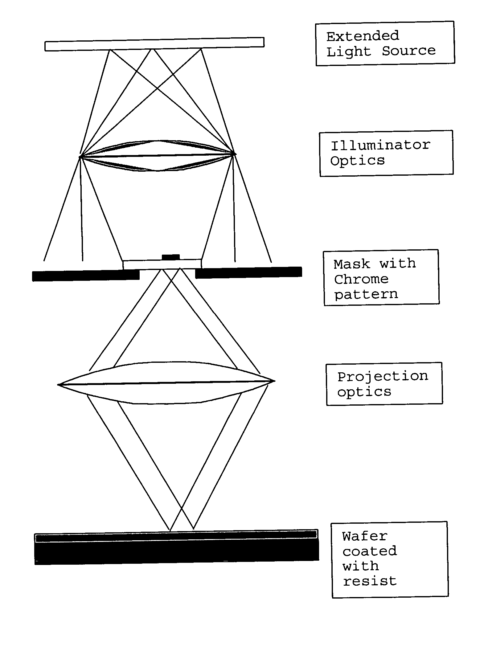
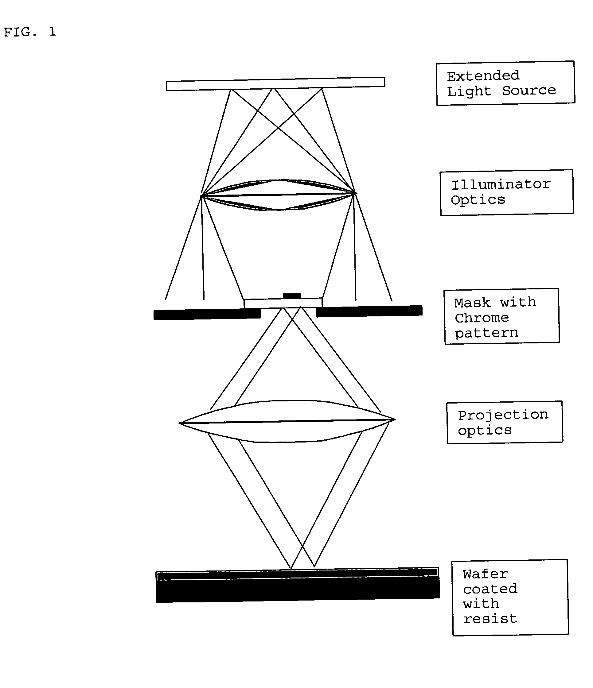
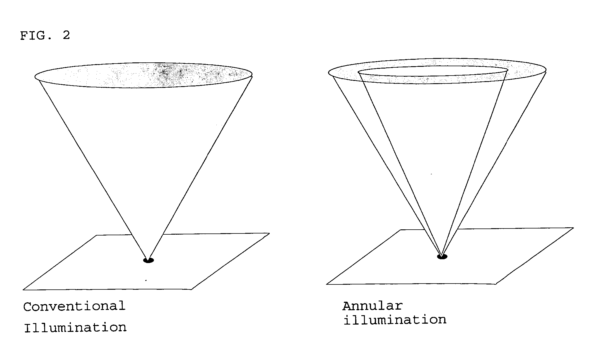
CROSS-REFERENCE TO RELATED APPLICATIONS [0001] Subject matter disclosed in this application might be considered to be related to subject matter disclosed in co-pending patent application Ser. No. 10 / 861,170 filed Jun. 4, 2004 and co-pending patent application Ser. No. 10 / 933,090 filed Sep. 1, 2004, both of which are assigned to the assignee of the present application and the entire disclosure of each of which is hereby incorporated by reference herein for all purposes.BACKGROUND OF THE INVENTION [0002] This invention relates to a method of characterizing lithography projection equipment used in manufacturing of integrated circuits. [0003] Referring to FIG. 1, a conventional optical lithographic scanner system, for image-wise exposure of a coating of resist on a semiconductor wafer, includes an extended light source for emitting a beam of actinic radiation. The illuminator optics project the light from the extended source onto an exposure mask (also called a reticle) that defines a p...

Claims


Application Information

Patent Timeline
Patent Type & Authority Applications(United States)
IPC IPC(8): G03B27/72
CPCG03B27/72G03F7/70133
Inventor ZACH, FRANZ X.WU, BOSEZGINER, ABDURRAHMAN
Owner CADENCE DESIGN SYST INC
Features
  • R&D
  • Intellectual Property
  • Life Sciences
  • Materials
  • Tech Scout
  • Unparalleled Data Quality
  • Higher Quality Content
  • 60% Fewer Hallucinations
Learn More