Optical signal communication apparatus

a communication apparatus and optical signal technology, applied in electrical devices, digital transmission, securing communication, etc., can solve the problems of high cost and difficult effective improvement of transmission speed, and achieve the effect of reducing the cost of data transmission system and improving the quality of transmission system

Inactive Publication Date: 2006-04-06
HITACHI LTD
View PDF5 Cites 15 Cited by
  • Summary
  • Abstract
  • Description
  • Claims
  • Application Information

AI Technical Summary

Benefits of technology

[0019] Since the encryption circuit and the data transmission circuit are separated from each other so as to be included in different systems, the single encryption circuit can be shared with a plurality of data transmission circuits. By sharing the high-cost encryption circuit, a reduction in costs of the data transm

Problems solved by technology

The encryption circuit employing the optical multi-value transmission, which is manufactured at the high cost and in which the effective improvement of the transmission speed

Method used


Image

  • Optical signal communication apparatus
  • Optical signal communication apparatus
  • Optical signal communication apparatus

Examples


first embodiment

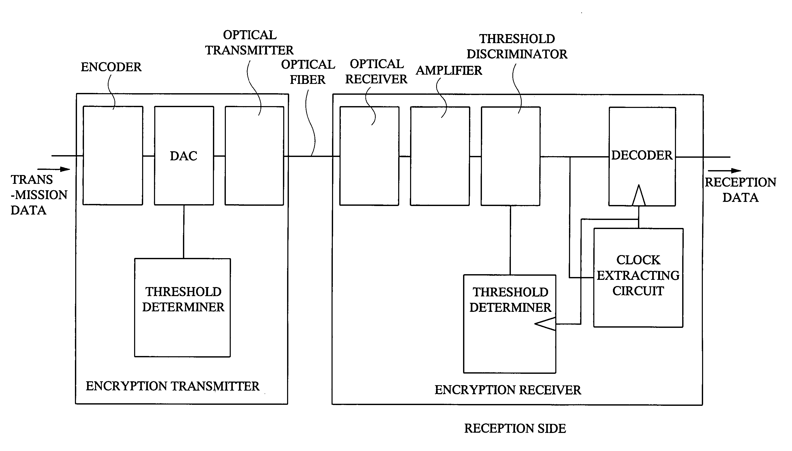
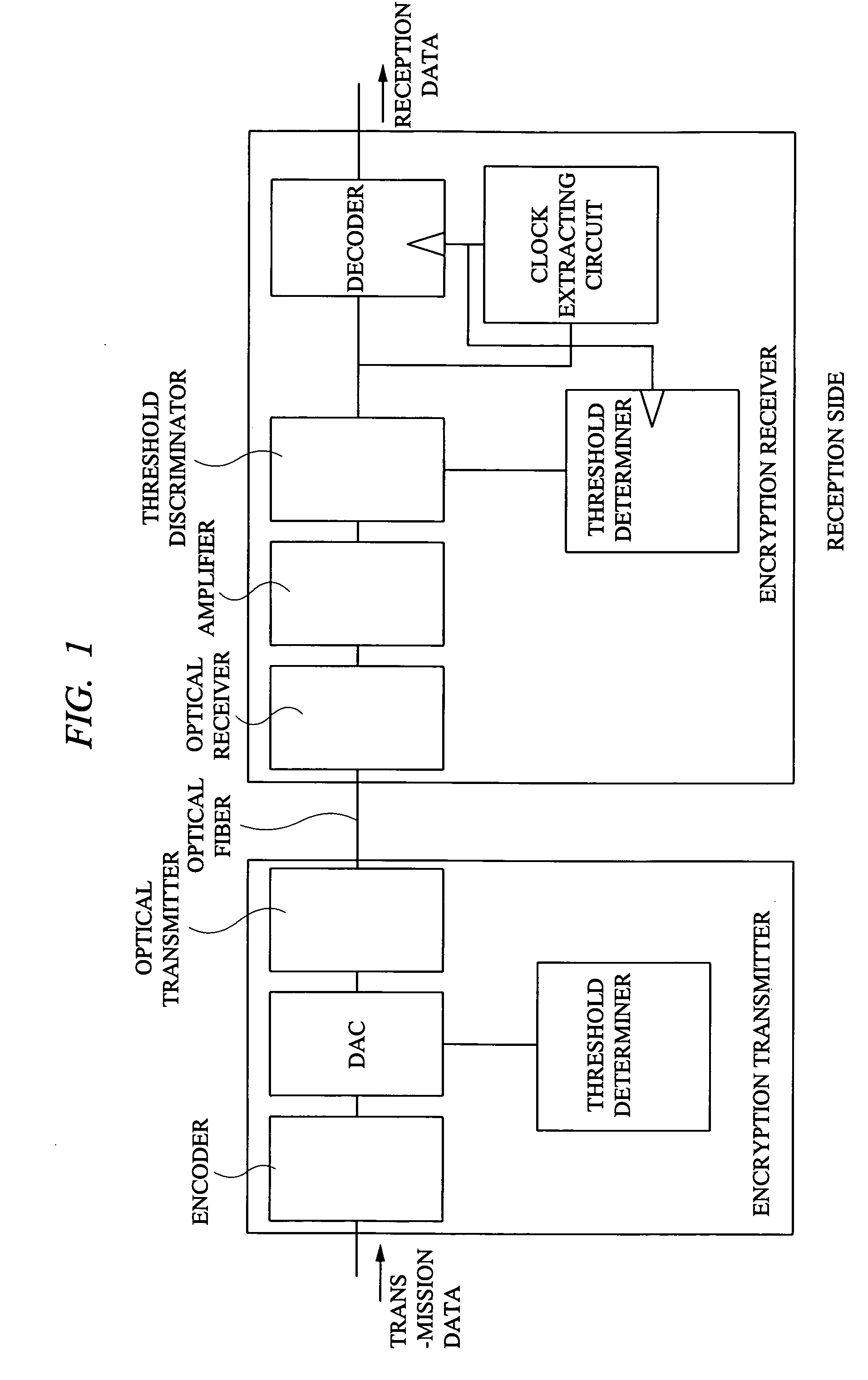
[0034] In a first embodiment, a transmitting unit and a receiving unit shown in FIG. 1 are used as an encryption transmission apparatus employing an optical multi-value transmission method. In an optical encrypted signal transmitting unit, transmission data composed of two-value digital data before encryption is converted into multi-value signals by a digital-to-analog converter (DAC) after scramble encoding is executed by an encoder. At a time of the conversion to the multi-value signals, a signal is generated in accordance with a logical threshold determiner connected to the DAC. An output from the DAC is converted into the multi-value signals at the optical transmitting unit and thereafter is sent into an optical fiber. An optical signal transmitted to the optical fiber is converted to an analog electric signal at the optical receiving unit. The electric signal from the optical receiving unit is converted to an electric signal with discriminable amplitude by an amplifier and ther...

second embodiment

[0041] The encrypted data transmission of the first embodiment involves transmission of a multi-value transmission over the optical transmission path. This causes the signal to be varied in the amplitude by the effects of thermal condition or physical disturbance and the drift characteristics of a laser transmitter or photodiode. It is hence desired to modify the threshold at the receiver side according to the modification of the signal amplitude.

[0042] Prior to the transmission of the encrypted data, reference signals for defining the upper and lower limits of the data are determined. FIG. 6 illustrates an example of the waveform of the reference signals. Assuming that the signal level of the multi-value has 9 levels, a reference signal 1 outputs the upper limit of signal intensity level 9 while a reference signal 2 outputs the lower limit of a signal intensity level 1. The two reference signals 1 and 2 may be varied due to the effect of the modification characteristics of the tra...

fourth embodiment

[0051] The data transmission apparatus of the first embodiment has three separate optical transmission systems to realize the signal transmission using fiber, respectively. In the embodiment shown in FIG. 11, the communication structure using three fibers are replaced by a combination of a wave mixer connected to the rear end of an optical transmitter equal to that of the first embodiment and a wave separator connected to the end of an optical receiver equal to that of the first embodiment. More specifically, the three laser emitters included in the optical transmitter of the encryption optical signal transmitter, the data transmitter 1, and the data transmitter 2 are set to different wavelengths.

[0052] This allows both the encryption communication and the two-value digital communication system to be carried out over a single fiber in a known multiple wavelength communication technique. Since this embodiment allows the overall transmission system to be structured with a single opti...


PUM


Abstract

In encryption transmission employing a conventional optical transmission apparatus, since a dedicated hardware unit to be used executes a complicated signal process, there are the problems that a high-speed transmission speed is difficult to realize and an entirety of a transmission system employing encryption becomes high in cost. An optical signal transmitter for encryption and an optical signal receiver for encryption, employing optical multi-value transmission which is high in cost and in which an effective improvement of transmission speed is difficult, are used only for exchanging an encryption key and data to be actually transmitted is transmitted by another line. A data signal is transmitted by using: the exchanged encryption key after communication of the encryption key is executed by using the transmitter and receiver for encryption transmission prior to the data transmission; and another system of high-speed signal transmission line in an encryption transmission circuit.

Description

CROSS-REFERENCE TO RELATED APPLICATION [0001] The present application claims priority from Japanese patent application No. JP 2004-292058 filed on Oct. 5, 2004, the content of which is hereby incorporated by reference into this application. BACKGROUND OF THE INVENTION [0002] The present invention relates to an internal structure of a communication apparatus for use in a computer network and particularly to a communication apparatus employing optical transmission paths. [0003] A variety of packet exchanging apparatuses called routers and switches, etc. have widely been used for establishing communication with computer networks. Recently, in such packet exchanging apparatuses, as a transmission speed of communication is increased, optical communication employing fiber optics is frequently used instead of using conventional electric (copper) cables. [0004] The optical communication employing the fiber optics is commonly used in a digital communication method called “PAM2”, in which one...

Claims


Application Information

Patent Timeline
IPC IPC(8): H04L9/00H04B10/556H04B10/85H04L9/08
CPCH04L9/0891H04L2209/08
Inventor NISHIMURA, SHINJI
Owner HITACHI LTD
Why Eureka
Try Eureka