
Unitized electrochemical cell sub-assembly and the method of making the same

a technology of electrochemical cells and sub-assemblies, which is applied in the direction of cell components, final product manufacturing, sustainable manufacturing/processing, etc., can solve the problems of reducing the performance of the electrochemical cell, metal ion contamination, and exposure of the membrane edge to ambient air

Inactive Publication Date: 2006-04-06
EI DU PONT DE NEMOURS & CO
View PDF32 Cites 27 Cited by
  • Summary
  • Abstract
  • Description
  • Claims
  • Application Information

AI Technical Summary

Benefits of technology

[0029] Numerous other objectives, advantages and features of the invention will become apparent to the person skilled in the art upon reading the detailed description of the preferred embodiments, the examples, and the claims.
[0042] e. ceasing to apply heat to cause the molten polymer to cool and harden around the edges of the ion exchange membrane, thereby sealing and joining the first and second plates to each other, and the first and second plates to the edges of the ion exchange membrane.

Problems solved by technology

Such designs typically result in exposure of the membrane edge to ambient air and / or cooling liquid as well.
Exposure of the membrane to ambient air can result in drying of the membrane and exposure to cooling liquid creates the possibility for metal ion contamination.
Both these effects reduce the performance of the electrochemical cell and lead to the mechanical degradation of the membrane.
Therefore, as discussed earlier, the vulnerability of the gaskets limiting the durability of the assembled cells still remains a limitation to the commercial success of the electrochemical cell.
The instability of many seal materials in the aggressive electrochemical cell environment is a significant problem.
It is a challenge to find a material that will provide the required durability for use in the electrochemical cell environment.
Some of the sealant materials used are not very stable in the reducing environment, such as on the anode side of the electrochemical fuel cell where hydrogen is consumed.
These materials work well on the air or oxidant side, but fail in the presence of hydrogen.
Particularly in the case of separator plates made of graphite or graphite composite, the adherence of the seal to the graphite is problematic.
There are several disadvantages associated with using sealant materials such as silicone rubber, RTV, E-RTV to seal the periphery of separator plates.
These sealant materials may not be compatible with the plate material used, which may be graphite, graphite composites or metals.
Over the course of an electrochemical cell's service life, the elastomeric gaskets are subjected to prolonged deformation and harsh operating environment.
Over time, such gaskets tend to decrease resilience, for example due to compression set and chemical degradation, and may become permanently deformed.
This impacts negatively on the sealing function and can ultimately lead to an increased incidence of leaks.
Material incompatibility may induce leakage around the sealant material, causing intermixing of reactant fluids and / or coolant fluid, resulting in failure of the cell.
Increased sealing pressure applied to the cells in the end plate areas may lead to increased plastic deformations and premature gasket and MEA failure.
Moreover, it is often difficult to correctly position the gaskets in the grooves or channels provided on the bi-separator plates or GDL using conventional manufacturing methods, thus also leading to deformation.
However, this patent does not describe a method of sealing together the separator plates of the fuel cell or a method of sealing the separator plates directly to the MEA.
However, the welding process does not describe a method of sealing two separator plates, while having a MEA sandwiched between them or a method of sealing separator plates to the MEA.
However, this does not describe a method for creating a rigid seal between two separator plates, which can hold both separator plates together maintaining the compressibility of the MEA.
However, this patent does not describe a method of sealing fuel cell separator plates without non-conductive frames.
Due to the presence of the same polymer in the non-conductive (sealing) and conductive regions, there is a possibility that the conductive part of the plate may get damaged during the sealing process, which usually involves evolution of heat.
However, the effectiveness of the seal is dependent on the flow characteristics of uncured RTV material and the curing properties, such as volumetric change of the material during curing process, in enclosed grooves.
However, the stability of these materials in the electrochemical cell environment, and the method and ease of assembling the components to make a unitized module was not disclosed.
This was done because none of the sealing materials could perform both edge and periphery sealing together.
However, the use of different sealing materials and their application steps makes the cell unitization process very time consuming and expensive, which is a hurdle to the commercialization of electrochemical cells.
However, there is no mention in this patent of obtaining improved sealing around the periphery of the electrochemical cell by using a recessed area in the plate.

Method used


Image

  • Unitized electrochemical cell sub-assembly and the method of making the same
  • Unitized electrochemical cell sub-assembly and the method of making the same
  • Unitized electrochemical cell sub-assembly and the method of making the same

Examples


example 1

[0082] A unitized cell was prepared by sandwiching a membrane electrode assembly (MEA) between two identical square pieces of composite plate parts comprising 25% Zenite® liquid crystal polymer resin, 55% Thermocarb® graphite powder and 20% graphite fibre. The parts had a length of 86.36 mm, width of 86.36 mm and a thickness of 1.78 mm. Recessed central areas having a length of 76.2 mm, a width of 76.2 mm and a depth of 0.127 mm were provided within both plate parts to accommodate the gas diffusion layers. An additional area of 5 mm around the perimeter of the recessed central areas was provided to be used as a sealing area. The composite plate parts were provided with corresponding holes at one corner of the plates to be used as a gas inlet or outlet for conducting the leak test of the unitized assembly. The diameter of the holes was 4.57 mm and they were each located at a distance of 12.7 mm away from both sides of the plates.

[0083] Two picture frame gaskets of 5.08 mm width of B...

example 2

[0091] A unitized cell was prepared using the tool and process described in Example 1 with the following exception: porous Kevlar® gaskets were placed between the membrane and Bynel® gaskets to prevent short circuit in the unitized assembly. The Kevlar® gaskets were cut with the same dimension as the Bynel® gaskets and were placed right below and above the Nafion® membrane. During the hot pressing process the molten Bynel® impregnated the porous matrix of Kevlar® and sealed it against Nafion® membrane.


PUM

PropertyMeasurementUnit
Pressureaaaaaaaaaa
Electrical conductoraaaaaaaaaa
aaaaaaaaaa

Abstract

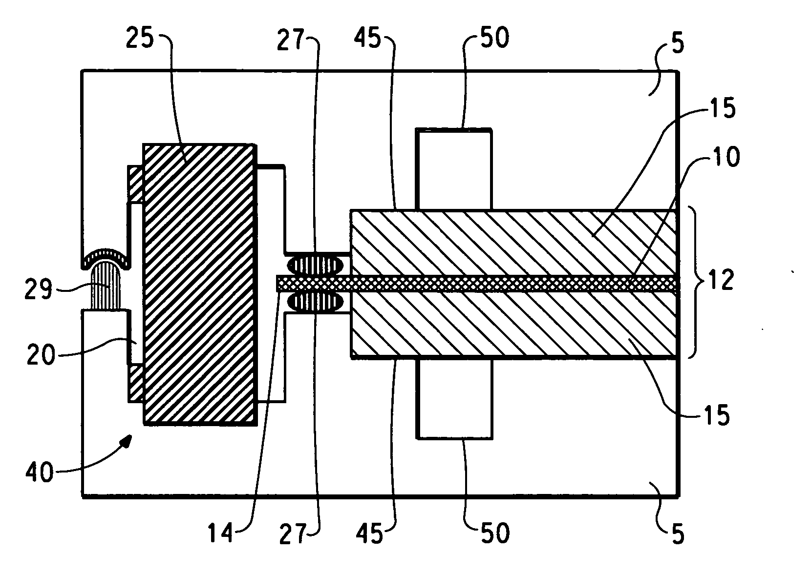
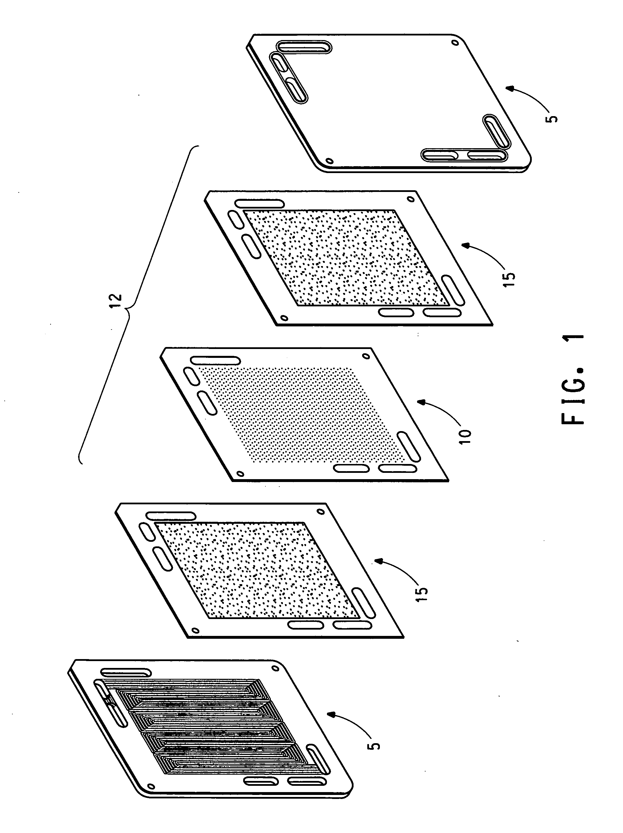
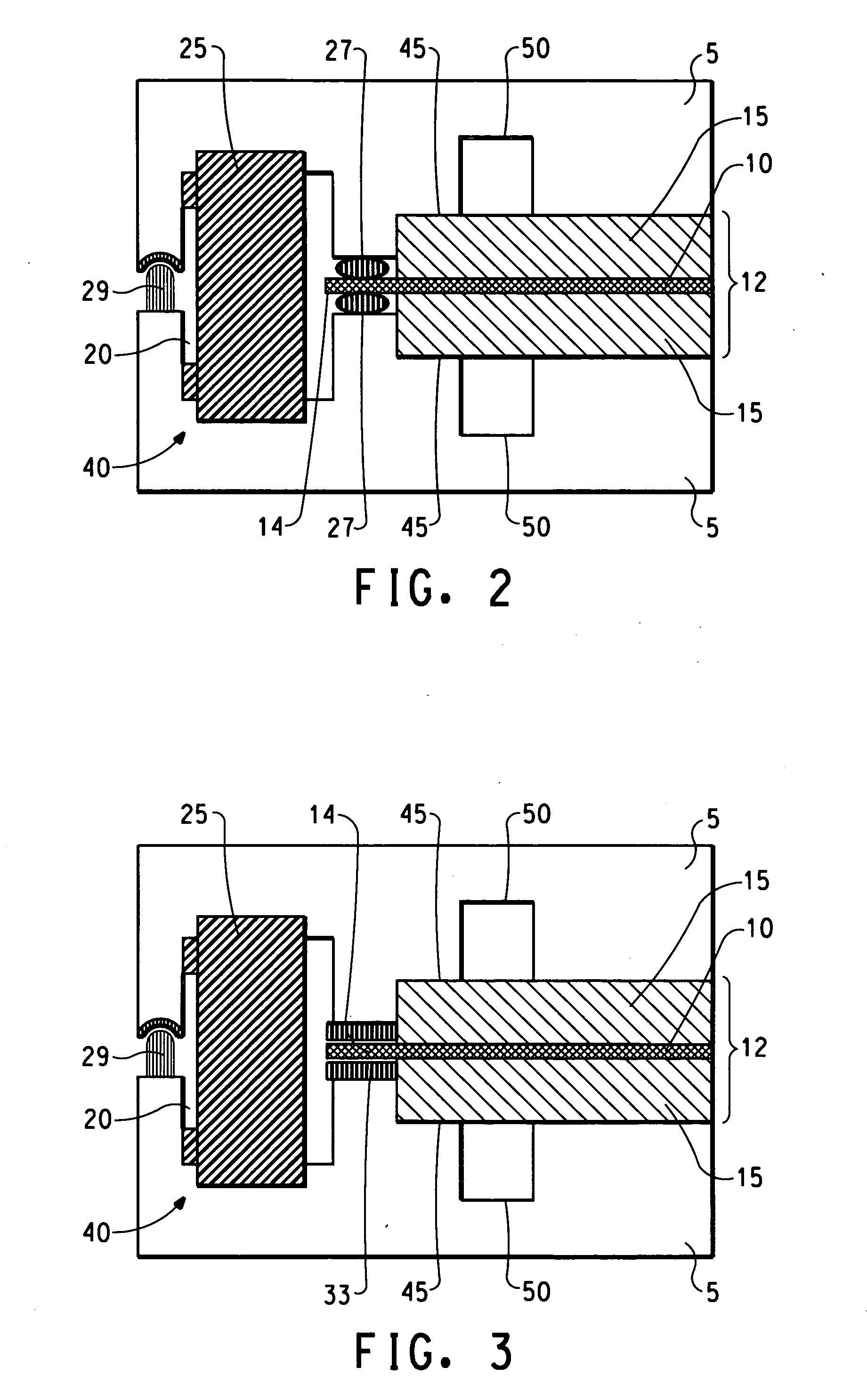
Disclosed is a unitized electrochemical cell sub-assembly having a first separator plate and a second separator plate that each has a first surface. A recess is located in at least one of the first surfaces to define a chamber adjacent the periphery of the plates when the plates face each other. A membrane electrode assembly (MEA) comprising an ion exchange membrane and a pair of gas diffusion layers is disposed on and between each of the first surfaces between the two plates when the plates face each other so that the peripheral edge of the ion exchange membrane is located within the chamber. Also located in the chamber is a non-conductive sealant polymer that seals and joins the first and second plates to each other, and that seals and joins the first and second plates to the edge of the ion exchange membrane. Also disclosed is a fabrication method for making the unitized electrochemical cell sub-assembly.

Description

FIELD OF THE INVENTION [0001] The present invention relates to a unitized electrochemical cell sub-assembly and more particularly to a unitized electrochemical cell sub-assembly formed by the integration of the separator and coolant plates with the membrane electrode assembly (MEA). Further this invention relates to methods for fabricating the unitized electrochemical sub-assembly that provide manufacturing simplification. BACKGROUND OF THE INVENTION [0002] Polymer electrolyte membrane fuel cells comprise a membrane electrode assembly (MEA) disposed between two current separator plates. Within the membrane electrode assembly lays a pair of fluid distribution layers, commonly referred to as gas diffusion layers (GDL) and an ion exchange membrane. At least a portion of either the ion exchange membrane or gas diffusion layers is coated with noble metal catalysts. The ion exchange membrane is placed between the gas diffusion layers and is compressed to form the membrane electrode assemb...

Claims


Application Information

Patent Timeline
IPC IPC(8): H01M2/08H01M8/10H01M8/02B05D5/12H01M8/24
CPCH01M8/0247H01M8/0271H01M8/0284H01M8/0286H01M8/1004H01M8/2405H01M2008/1095Y02E60/521Y02E60/50Y02P70/50H01M8/0273
Inventor ANDRIN, PETERCHOUDHURY, BISWAJITGHOSH, KALYANHOOPER, MIKE A.PERTI, DEEPAKBRUNK, DONALD H.OTTENHOF, JAN
Owner EI DU PONT DE NEMOURS & CO
Learn More