Receiving device, semiconductor integrated circuit, transmitting/receiving device, transport apparatus portable transmitting/receiving device, communication system and receiving method

a technology of transmitting/receiving device and semiconductor integrated circuit, which is applied in the direction of transmission monitoring, instruments, high-level techniques, etc., can solve the problem of not being able to reduce the power consumption of the receiver circuit, and achieve the effect of reliable performan

Inactive Publication Date: 2006-04-06
PANASONIC CORP
View PDF11 Cites 24 Cited by
  • Summary
  • Abstract
  • Description
  • Claims
  • Application Information

AI Technical Summary

Benefits of technology

[0060] Moreover, according to the receiving method of the present invention, it is preferable that the fifth step includes the step of notifying that the level of the reception electric field intensity signal is equal to or higher than the second threshold. For example, in an ETC system, when the receiving device approaches a tollgate, i.e., a base station, it is notified that the level of the reception electric field intensity signal has exceeded the second threshold, thereby preventing a failure of placing an external component such as a pay card or the like. Thus, exchange information at the tollgate can be reliably performed.

Problems solved by technology

Therefore, in the known technology, power consumption of a receiver circuit can not be reduced.

Method used


Image

  • Receiving device, semiconductor integrated circuit, transmitting/receiving device, transport apparatus portable transmitting/receiving device, communication system and receiving method
  • Receiving device, semiconductor integrated circuit, transmitting/receiving device, transport apparatus portable transmitting/receiving device, communication system and receiving method
  • Receiving device, semiconductor integrated circuit, transmitting/receiving device, transport apparatus portable transmitting/receiving device, communication system and receiving method

Examples


first embodiment

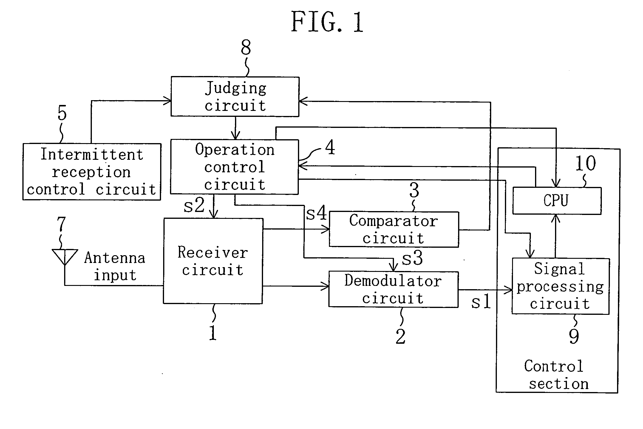
[0086]FIG. 1 is a block diagram illustrating an exemplary configuration of a receiving device according to a first embodiment of the present invention. As shown in FIG. 1, the receiving device of this embodiment includes a receiver circuit 1 for receiving a signal transmitted from a base station (not shown) via an antenna 7 and outputting an electric field intensity of a received signal as a reception electric field intensity signal and a demodulator circuit 2 for demodulating the signal processed by the receiver circuit 1. Moreover, the receiving device of this embodiment also includes a comparator circuit 3 for comparing a level of the reception electric field intensity signal output from the receiver circuit 1 to a first threshold and a second threshold and making a judgment and an intermittent reception control circuit 5 for outputting a signal for intermittently operating the receiver circuit 1. In this case, the intermittent reception control circuit 5, in other words, outputs...

second embodiment

[0112] As a second embodiment of the present invention, a hysteresis control used in a receiving device according each embodiment of the present invention will be described.

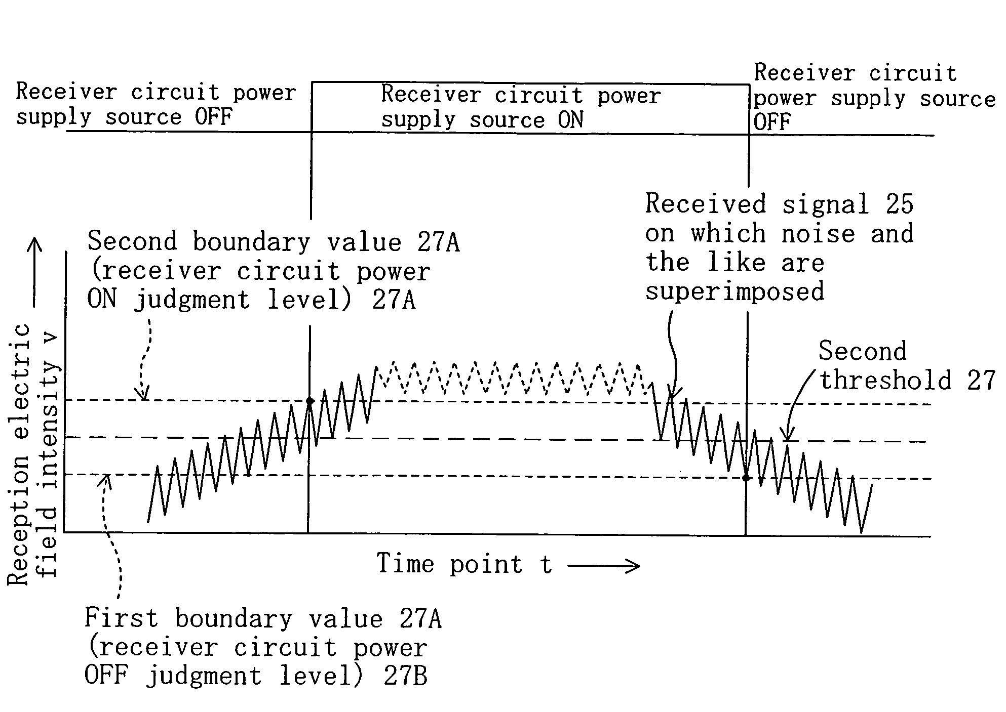
[0113]FIG. 3 is a diagram illustrating a method for judging a reception start level v2 (second threshold 27) in a receiving device according to the second embodiment. As shown in FIG. 3, a signal received by the receiver circuit 1 contains noise and the like and the reception electric field intensity v of the received signal varies depending on a measuring time point. Thus, in the receiving device of FIG. 1, if the comparator circuit 3 judges the level of the reception electric field intensity signal 25 based on the second threshold of a single value, there might be cases where an accurate operation of the receiver circuit 1 can not be performed. That is, because of the influence of noise, there might be cases where with a threshold assumed as a boundary, the reception electric field intensity v fluctuates up an...

third embodiment

[0117] Hereinafter, a receiving device according to a third embodiment of the present invention will be described with reference to FIG. 4. Note that detail also described in the first embodiment and the detail description of each member also shown in FIG. 1 will be omitted.

[0118]FIG. 4 is a block diagram illustrating the configuration of the receiving device of the third embodiment of the present invention. As shown in FIG. 4, the receiving device of this embodiment includes a receiver circuit 1 for outputting a signal received via an antenna 7 as a reception filed intensity signal, a demodulator circuit 2 for demodulating the signal processed by the receiver circuit 1 and outputting the signal, a comparator circuit 3 for comparing the level of the reception electric field intensity signal output from the receiver circuit 1 with a first threshold and a second threshold and judging the level of the reception electric field intensity signal, an intermittent reception control circuit...


PUM


Abstract

A receiving device includes a receiver circuit for outputting a received signal as a reception electric field intensity signal, an operation control circuit for controlling an operation of the receiver circuit, and an intermittent reception control circuit for outputting a periodic signal. A comparator circuit holds a first threshold indicating that the receiving device has entered a communication area and a second threshold indicating a start of a continuous electric field intensity measurement. If the reception electric field intensity signal is lower than the second threshold, the operation control circuit makes the receiver circuit perform intermittent operation. If the reception electric field intensity signal is equal to or higher than the second threshold, the operation control circuit makes the receiver circuit perform a continuous operation. If the reception electric field intensity signal is equal to or higher than the first threshold, the operation control circuit makes the demodulation circuit perform an operation.

Description

CROSS-REFERENCE TO RELATED APPLICATION [0001] This application claims priority under 35 U.S.C. §119(a) on Japanese Patent Application No. 2004-291981 filed on Oct. 4, 2004 and Japanese Patent Application No. 2005-179779 filed on Jun. 20, 2005, the entire contents of which are hereby incorporated by reference. BACKGROUND OF THE INVENTION [0002] 1. Field of the Invention [0003] The present invention relates to a receiving device used for small area communication, represented by dedicated short range communication and wireless LAN communication, and a transmitting / receiving device, a transport apparatus and communication system including the receiving device. [0004] 2. Prior Art [0005]FIG. 23 is a block diagram illustrating the configuration of known vehicle-mounted communication system used for dedicated short range communication and the like. The vehicle-mounted communication system of FIG. 23 includes a control section 171 including a CPU 172 and a signal processing circuit 173, a t...

Claims


Application Information

Patent Timeline
Patent Type & Authority Applications(United States)
IPC IPC(8): H04M1/00G07B15/06
CPCG07B15/063H04W52/0245Y02D30/70H04B1/06H04L12/28
Inventor HANABUSA, MIKIOWATANABE, KAZUNORIISHIDA, KAORU
Owner PANASONIC CORP
Why Eureka
Try Eureka