
In VIVO sensor and method of making same

Inactive Publication Date: 2006-04-06
VACTRONIX SCI LLC
View PDF57 Cites 101 Cited by
  • Summary
  • Abstract
  • Description
  • Claims
  • Application Information

AI Technical Summary

Benefits of technology

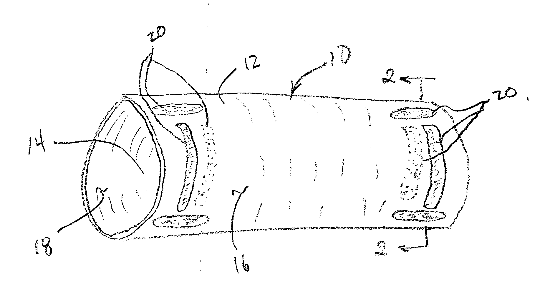
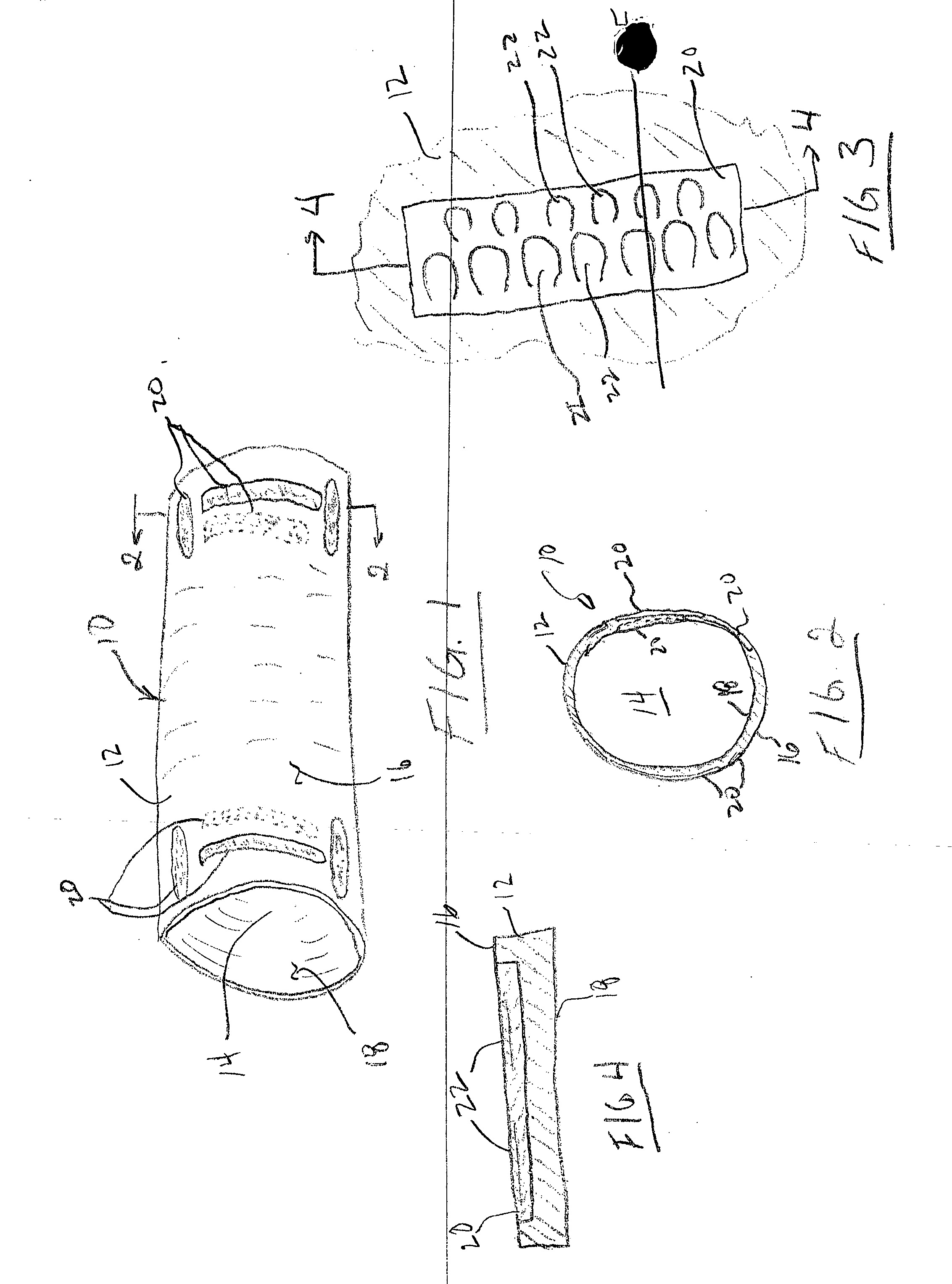
[0023] In another particular form the invention, the sensor comprises a plurality of cantilever members positioned on at least one of the proximal, distal or intermediate regions of the endoluminal device and positioned on at least one of the luminal or abluminal wall surfaces of the endoluminal device. To facilitate ease of detection, a plurality of groups of cantilever members are provided, each group is formed of a plurality of individual cantilever members, with each individual cantilever members in the group having identical transition temperatures. The plurality of groups of cantilever members are arrayed along the longitudinal axis of the endoluminal device in such a manner as to create a continuum of groups of cantilever members having different stress-strain transition pressures. Changes in applied stress or strain, such as blood pressure or blood flow shear stress, at the site of the endoluminal device are indicated by the stress and strain acting on the cantilever members or groups of cantilever members which provides a corresponding frequency shift in energy reflected, when compared to a baseline stress-strain for unloaded cantilever members. The position and frequency shift of the cantilever members may be determined by radiography, ultrasonography, magnetic resonance imaging or other means which provides a detectable image of the position of the individual cantilever members and groups of cantilever members or is capable of measuring frequency shifts due to differential stress-strain loading onto the cantilever members.

Problems solved by technology

Welding, however, is generally not an acceptable method for joining nickel-titanium alloys to other materials, e.g., stainless steel, because brittle intermetallics may be formed in the weld zone.

Method used


Image

  • In VIVO sensor and method of making same
  • In VIVO sensor and method of making same
  • In VIVO sensor and method of making same

Examples


Embodiment Construction

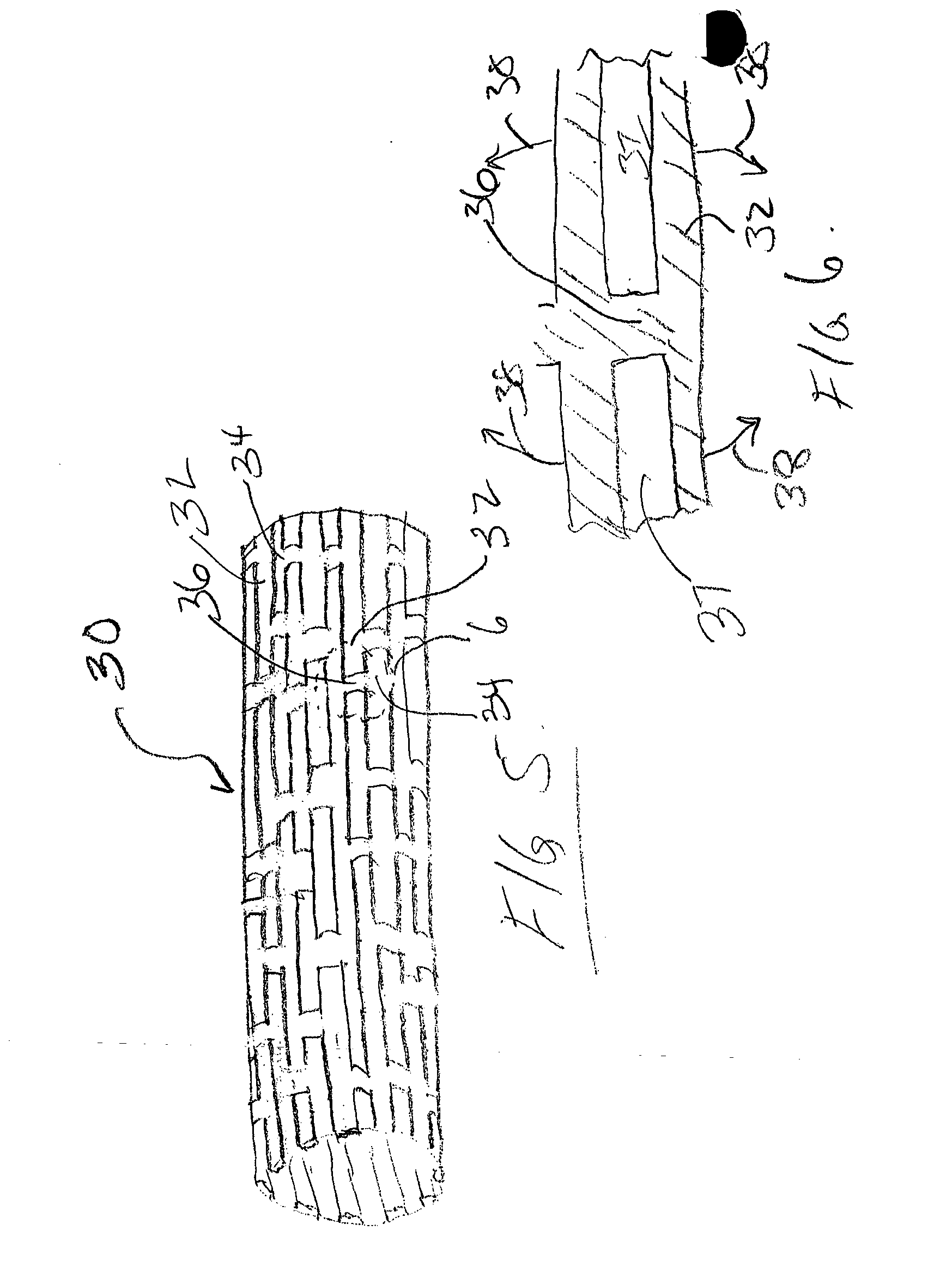
[0040] To simplify description of the present invention, most of the preferred embodiments will be described with reference to an endoluminal stent, except where otherwise stated. However, those of ordinary skill in the art will understand that each embodiment has application to a variety of implantable devices including, without limitation, stents, grafts, stent-grafts, valves, shunts or patches.

[0041] The particular means for detecting a change in the inventive sensor and / or the particular means for activating a change in the inventive sensor is generally not considered part of the present invention. For example, it is known that ultrasound energy may be employed to generate both one-way and two-way shape memory effects in nickel-titanium alloys. V. V. Klubovich, V. V. Rubanick, V. G. Dorodeiko, V. A. Likhachov, and V. V. Rubanick Jr. (Institute of Tech. Acoustics, 13 Ludnikova, 210026 Vitebsk, Belarus,) Generation of Shape Memory Effect in Ti—Ni Alloy by means for Ultrasound, Ab...


PUM

PropertyMeasurementUnit
Temperatureaaaaaaaaaa
Forceaaaaaaaaaa
Pressureaaaaaaaaaa

Abstract

Implantable in vivo sensors used to monitor physical, chemical or electrical parameters within a body. The in vivo sensors are integral with an implantable medical device and are responsive to externally or internally applied energy. Upon application of energy, the sensors undergo a phase change in at least part of the material of the device which is then detected external to the body by conventional techniques such as radiography, ultrasound imaging, magnetic resonance imaging, radio frequency imaging or the like. The in vivo sensors of the present invention may be employed to provide volumetric measurements, flow rate measurements, pressure measurements, electrical measurements, biochemical measurements, temperature, measurements, or measure the degree and type of deposits within the lumen of an endoluminal implant, such as a stent or other type of endoluminal conduit. The in vivo sensors may also be used therapeutically to modulate mechanical and / or physical properties of the endoluminal implant in response to the sensed or monitored parameter.

Description

BACKGROUND OF THE INVENTION [0001] The present invention relates generally to the field of implantable medical devices, and more particularly pertains to sensors that may be implanted into a body to elicit at least one of a mechanical, chemical or electrical response to an in vivo physiological condition or state with the body. The present invention provides a vacuum deposited film which may be either a monolithic monolayer of material or a multilayered film having at least portions of the film capable of sensing at least one of changes in temperature, pressure, or the presence or absence of chemical or biochemical species in the body by mechanical, electrical, chemical, electrochemical or electromechanical means. [0002] Specifically, the present invention relates to the manufacture and use of implantable sensors to monitor physical, chemical or electrical parameters of a fluid flow through a body passageway. For example, the sensors of the present invention may be employed to provi...

Claims


Application Information

Patent Timeline
IPC IPC(8): A61F2/06A61B5/00A61B5/01A61B5/0215A61B5/06A61B5/07A61B17/00A61F2/82A61L27/00A61L27/04A61L31/02A61M1/10
CPCA61B5/01A61B5/0215A61B5/076A61B5/6862A61B5/6876A61F2/82A61F2/91A61L27/04A61L31/022A61F2250/0096A61F2310/00023A61B5/02035A61B5/4842A61B5/021A61B5/14532A61B5/145A61B5/02A61F2210/0023A61F2250/0029A61F2250/0001A61F2210/0076A61F2210/0014A61F2210/0042A61F2250/0004A61F2250/0018A61F2250/0035A61F2250/0042A61F2250/0014A61F2250/0067A61B5/02427A61B5/14503A61F2002/4672A61B5/6846A61F2250/0068A61F2250/0098A61B5/0507A61B5/1473A61B6/12A61B8/0841A61B2562/0247A61B2562/0276A61B2562/12A61B2562/164A61F2/958B23K1/19
Inventor BAILEY, STEVEN R.BOYLE, CHRISTOPHER T.MARTON, DENESBANAS, CHRISTOPHER E.
Owner VACTRONIX SCI LLC
Learn More