Image forming apparatus

a technology of image forming apparatus and forming device, which is applied in the direction of electrographic process apparatus, ohmic resistance heating, instruments, etc., can solve the problems of insufficient heat supply to the influence of the fixing capability of the toner image on the transfer material in the fusing device, and the inability to achieve the fixation performance. , to achieve the effect of enhancing responsiveness, reducing power consumption or energy saving, and improving accuracy

Active Publication Date: 2006-04-13
CANON KK
View PDF10 Cites 203 Cited by
  • Summary
  • Abstract
  • Description
  • Claims
  • Application Information

AI Technical Summary

Benefits of technology

[0024] It is therefore an object of the present invention to provide an image forming apparatus that solves the aforementioned first problem and can control the amount of power to be supplied to a ceramic planar heater of a fusing device below a maximum applicable current value specified for the ceramic planar heater.
[0025] Another object of this invention is to meet the requirement of the second problem and make it possible to automatically set optimum fixing conditions (image heating conditions) irrespective of paper kind, particularly a surfaceness of a transfer material (print medium).
[0026] Still another object of this invention is to provide an image forming apparatus that can solve the aforementioned third problem and improve a detection accuracy of an input current to the fusing device.
[0032] With the above construction, the present invention can set an upper limit on a maximum applicable power according to variations in an input supply voltage and a resistance of the heating means, which in turn enables a highest allowable power in a particular condition to be supplied to the heating means.
[0033] Further, with the image fusing device of this invention, it is possible to automatically set an optimum image fusing condition (fixing condition) independently of paper kind, particularly a a surfaceness of a print medium or transfer material. This produces an effect of a reduced power consumption or energy saving.
[0034] Further, this invention can detect an input current with an improved accuracy and enhance a responsiveness, contributing to a finer or more precise control.

Problems solved by technology

As to the control of a current supplied to the heater of the fusing device, however, there are the following problems.
A first problem is that the ac power to be supplied to the ceramic planar heater has a wide voltage range of, for example, 85V-140V or 187V-264V.
A second problem is that the fixing capability of a toner image on the transfer material in the fusing device is known to be influenced greatly by the thickness and surface roughness of the transfer material.
Paper with a rough surface in particular has a significantly degraded fixing performance.
This is caused by the fact that a reduced contact area between the heating member and the paper in the nip portion results in a sufficient amount of heat failing to be supplied to the toner on the transfer material.
However, increasing the fixing pressure tends to increase a drive torque of the fusing device and therefore the device cost.
On the other hand, simply increasing the fixing temperature to obtain an improved fixing performance can result in an excessive amount of heat being supplied to thin paper and paper with good surface.
This in turn causes problems such as hot offsets and increased curling of paper.
Optimum fixing requirements for both kinds of paper with rough surface and with smooth surface are difficult to satisfy and the conventional practice involves selecting an appropriate fixing temperature setting according to the kind of paper on the part of the user.
However, setting the fixing mode using the surface roughness, a parameter that the user cannot easily-understand, is not easy and there has been a call for a capability of automatically performing an appropriate fixing temperature setting according to the kind of paper.
A third problem is that since an output voltage of the current transformer T1 is full-wave rectified, it is very difficult to detect a current particularly when a phase control, which is often performed during a power control in an image forming apparatus, is executed.
Therefore, the control of current supplied to the heater in the fusing device may become inaccurate.

Method used


Image

  • Image forming apparatus
  • Image forming apparatus
  • Image forming apparatus

Examples


embodiment 1-1

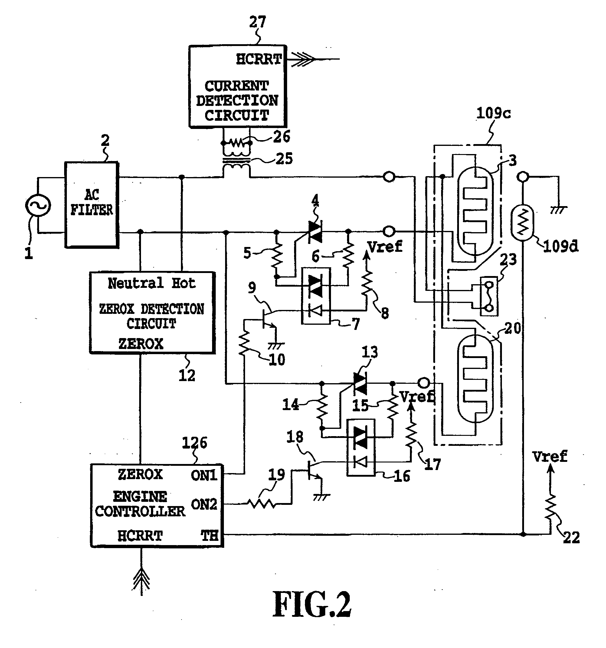
[0063]FIG. 2 is a block diagram of embodiment 1-1 of this invention. This represents an example temperature control circuit to control a temperature of a ceramic planar heater as a heat source of the fusing device. A construction of a laser beam printer incorporating this temperature control circuit is shown in FIG. 3.

[0064]FIG. 3 is explained in the following. A laser beam printer 101 has a cassette 102 accommodating print paper S, a cassette sensor 103 for detecting the presence or absence of print paper S in the cassette 102, a cassette size sensor 104 (made up of a plurality of microswitches) for detecting the size of the print paper S in the cassette 102, and a feed roller 105 for feeding print paper S from the cassette 102.

[0065] Arranged downstream of the feed roller 105 is a resist roller pair 106 for synchronously transporting the print paper S. Downstream of the resist roller pair 106 is installed an image forming unit 108 that forms a toner image on the print paper S ac...

embodiment 1-2

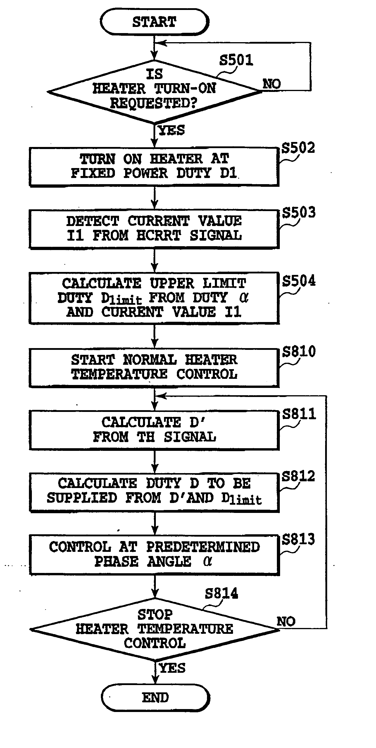
[0093]FIG. 9 is a flow chart showing an outline of a control sequence for the fusing device in this embodiment. In FIG. 9 steps S501 to S504 are the same as in FIG. 6A to E of FIG. 10 and A to E of FIG. 11 illustrate schematic operation waveforms of a heater current and ON1 and ON2 signals. A to E of FIG. 10 represent operation waveforms when an input voltage is low within the predetermined voltage range. A to E of FIG. 11 represent operation waveforms when the input voltage is high. In the following description, we will refer only to the operation waveforms of A to E of FIG. 10.

[0094] When a request to start power supply to the ceramic planar heater 109c occurs (step S501), the engine controller 126 energizes the heating bodies 3, 20 with the same, fixed duty D1 (S502). At a phase angle α1 corresponding to the fixed duty D1, ON-pulses of ON1 and ON2 signals with a ZEROX signal as a trigger are issued from the engine controller 126 (see B and C of FIG. 10). The ceramic planar heate...

embodiment 2-1

[0124] (1) Example of Image Forming Apparatus

[0125]FIG. 12 is a schematic diagram showing an image forming apparatus in this embodiment. This image forming apparatus is a laser beam printer based on a transfer electrophotographic process.

[0126] Denoted 2101 is a photosensitive drum carrying electrostatic charges and 2105 is a laser scanner as an image exposing device. In this laser scanner, reference number 2102 represents a semiconductor laser as a light source, 2103 a rotatable multi-faced mirror that is rotated by a scanner motor 2104, and L a laser beam emitted from the semiconductor laser 2102 and adapted to scan over the photosensitive drum 2101.

[0127] Designated 2106 is a charge roller 2106 to uniformly charge the surface of the photosensitive drum 2102. The surface of the photosensitive drum 2101 uniformly charged by the charge roller 2106 is scanned and exposed by the output leaser beam L from the laser scanner 2102 to form an electrostatic latent image of target image i...


PUM


Abstract

This invention is intended to control the amount of power to be supplied to a fusing heater below a maximum applicable current value. The engine controller supplies electricity to both of two heating bodies at the same fixed duty D1. At a phase angle al corresponding to the fixed duty D1, pulse signals ON1 and ON2 are issued in response to a ZEROX signal as a trigger. A current value I1 is detected based on a HCRRT signal from the current detection circuit. The engine controller calculates an upper limit of applicable power duty Dlimit based on the detected current value I1, the fixed duty D1 and the preset applicable current value Ilimit. Then, a PI temperature control is performed at a duty below the upper-limit duty Dlimit.

Description

[0001] This application claims priority from Japanese Patent Application Nos. 2003-012586 filed Jan. 21, 2003, 2003-098565 filed Apr. 1, 2003 and 2003-056997 filed Mar. 4, 2003, which are incorporated hereinto by reference. BACKGROUND OF THE INVENTION [0002] 1. Field of the Invention [0003] The present invention relates to an electrophotographic image forming apparatus and more specifically to a control of electric current supplied to a heater in a fusing device that heats and fixes a toner image carried on a recording medium. [0004] 2. Description of the Related Art [0005] An image forming apparatus using an electrophotographic process has been known. In this image forming apparatus, an unfixed image (toner image) formed on a recording medium (print paper) by an image forming means such as the electrophotographic process is fixed on the paper by a fusing device. Among known fusing devices are a heat roller type fusing device using a halogen heater and a film heating type fusing dev...

Claims


Application Information

Patent Timeline
Patent Type & Authority Applications(United States)
IPC IPC(8): G03G15/20G03G15/00
CPCG03G15/2039
Inventor KAWAZU, TAKAOTAKAHASHI, ATSUYAMOCHIZUKI, MASATAKA
Owner CANON KK
Why Eureka
Try Eureka