Composite material consisting of intermetallic phases and ceramics and production method for said material

a technology of which is applied in the field of composite materials comprising intermetallic phases and ceramics, can solve the problems of insufficient adhesion of layers to the base material, inability to manufacture, and inability to meet the requirements of the application, and achieves the effects of high ductility, high hardness, and economical and rapid process for manufacturing

Active Publication Date: 2006-04-13
DAIMLER AG
View PDF7 Cites 31 Cited by
  • Summary
  • Abstract
  • Description
  • Claims
  • Application Information

AI Technical Summary

Benefits of technology

[0010] It is thus the task of the invention to provide a temperature stable and wear resistant component, or a corresponding material layer of a composite...

Problems solved by technology

A disadvantage of the LDS spray layers and the spray compacting for production of layers and semi-finished products are, until now, the insufficient adhesion of the layers to the base material (substrate), the high brittleness, the high porosity and the inhomogeneities of the layers.
Particularly disturbing is the tendency towards formation of cracks in thicker layers, that is, greater than 1 mm thickness.
The basic principle of LDS is at the time strongly limited by the selection of materials for ...

Method used


Image

  • Composite material consisting of intermetallic phases and ceramics and production method for said material
  • Composite material consisting of intermetallic phases and ceramics and production method for said material
  • Composite material consisting of intermetallic phases and ceramics and production method for said material

Examples


example 1

ILLUSTRATIVE EXAMPLE 1

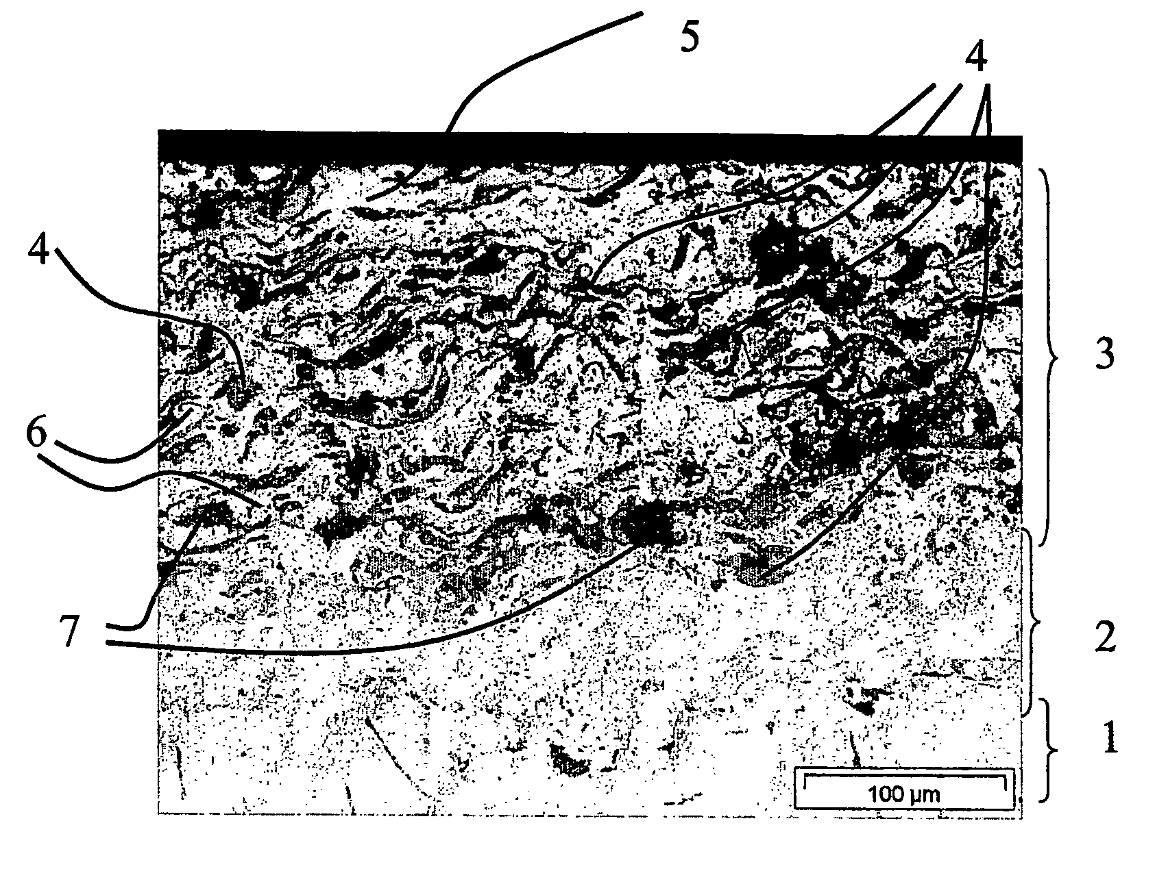
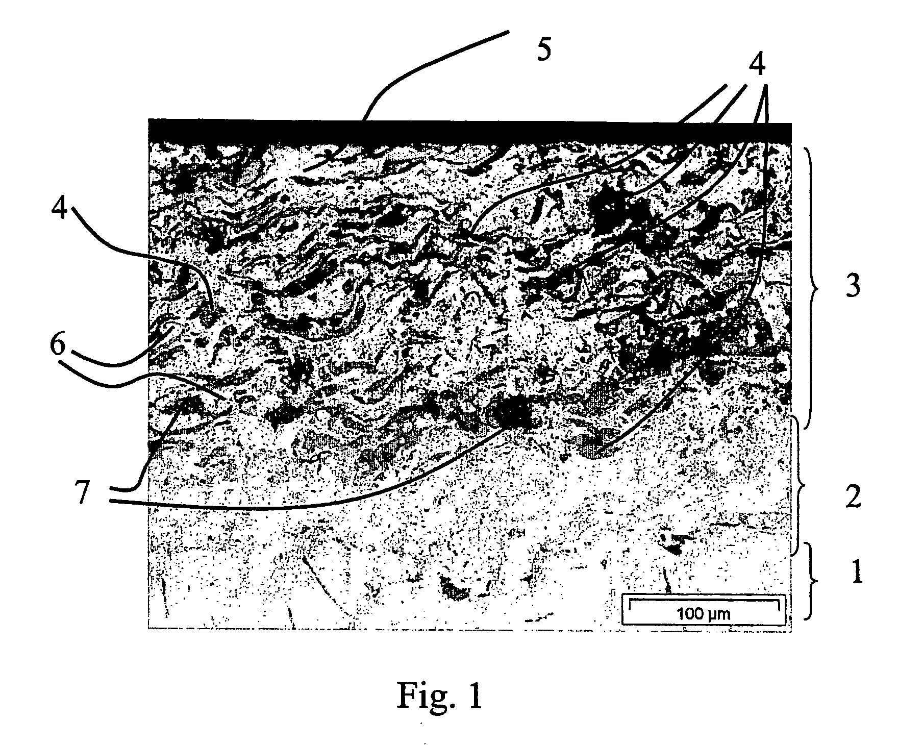
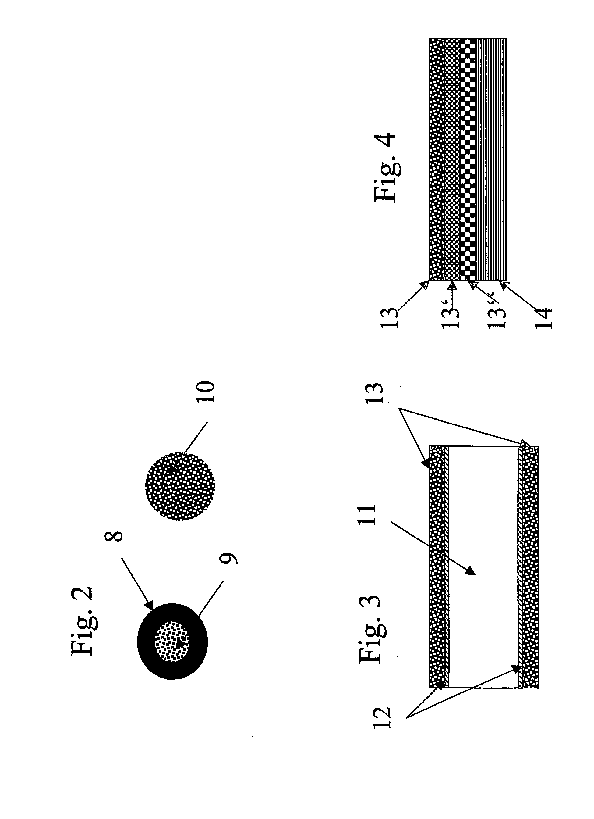
[0073] This illustrative Example is concerned with the manufacture of a high capacity brake disc for motor vehicles. For this, the brake disc was produced by the combination of a conventional gray cast iron brake disc with a friction layer of a titanium aluminide / aluminum oxide composite material. A conventional gray cast iron brake disc was prepared for coating by sandblasting. For the LDS process two different wires were employed. Wire 1, the metallic wire, was comprised of conventional NiTi5. Wire 2, the composite wire, was comprised of a metallic jacket and a ceramic core. The metallic jacket was formed by Al (purity greater than 99.5%) and the core by titanium oxide (TiO2) particles (Rutil) with an average particle size in the range of 2 to 5 μm. The wire was composed of 72 wt. % of jacket material and 28 wt. % filler. The wire was obtained by stretching a titanium oxide particle filled aluminum metal jacket.

[0074] The diameter of both wires was 1.6 mm.

[...

example 2

ILLUSTRATIVE EXAMPLE 2

[0080] Illustrative Example 2 concerns the manufacture of a shaft of a spray compacted bolt provided with a wear resistant coating.

[0081] As base or substrate for building the bolt a steel plate with a ground surface was employed. Thereupon, by spray compacting in known manner in multiple layers, a bolt or stud is deposited.

[0082] The wear resistant protective layer was produced by the inventive LDS process with two wires. As wire 1 a conventional NiTi5 wire with a diameter of 1.5 mm was employed. As wire 2 a composite wire comprised of 65 wt. % Al (purity 99.5%)and 35 wt. % titanium oxide (Rutil, with an average particle diameter of 2 to 5 Mm) was employed. The Al formed a dense jacket for the core comprised of titanium oxide. The diameter of the composite wire was 2 mm. The two wires were supplied to the LDS-nozzle with the same and constant speed.

[0083] For examination of the material characteristics of the deposited composite material, the bolt and subst...


PUM

PropertyMeasurementUnit
Fractionaaaaaaaaaa
Thicknessaaaaaaaaaa
Wear resistanceaaaaaaaaaa

Abstract

The invention concerns a composite material consisting of intermetallic phases and ceramic, in particular in the form of a coating on metallic substrates, as well as an arc wire spraying process for production of the composite material in which the intermetallic phases and the ceramics to be deposited are newly formed during the deposit process from the components of the supplied wires by chemical reaction. The invention further concerns wear resistant layers formed by the composites, tribologic layers and plating or hard-facing materials.

Description

BACKGROUND OF THE INVENTION [0001] 1. Field of the Invention [0002] The invention concerns a composite material comprising intermetallic phases and ceramic, in particular in the form of a coating on a metallic substrate, as well as an arc wire spraying process for production of the composite material in which the intermetallic phases and the ceramics to be deposited are newly formed during the deposit process from the components of the supplied wires by chemical reaction. The invention further concerns wear resistant layers formed by the composites, tribologic layers and plating or hard-facing materials. [0003] 2. Related Art of the Invention [0004] In the production of material layers, the arc wire spraying process or the thermal spray process is characterized by a simple process management and high deposit rate. The coating of components close to their final contours of economical materials by means of arc wire spraying (LDS) satisfies many aspects of the requirements for producti...

Claims


Application Information

Patent Timeline
IPC IPC(8): B32B15/04B32B9/00B32B19/00B05D1/08B05D7/00C23C4/12F16D69/02F41H5/04
CPCC23C4/125F16D69/027Y10T428/12736F16D65/12F16D2250/0046F41H5/0421C23C4/131Y10T428/31678
Inventor GRAU, STEFANSCHEYDECKER, MICHAELWEISSKOPF, KARL
Owner DAIMLER AG
Why Eureka
Try Eureka