Externally-applied patient interface system and method

a patient interface and external application technology, applied in the field of external application of patient interface system and method, can solve the problems of tissue separation, dead space problems more apt to occur, and deeper incisions may well require not only skin surface closure, but also time-consuming placement of multiple layers of sutures, etc., to enhance the closure of separated tissue portions

Inactive Publication Date: 2006-04-13
KCI LICENSING INC
View PDF99 Cites 734 Cited by
  • Summary
  • Abstract
  • Description
  • Claims
  • Application Information

AI Technical Summary

Benefits of technology

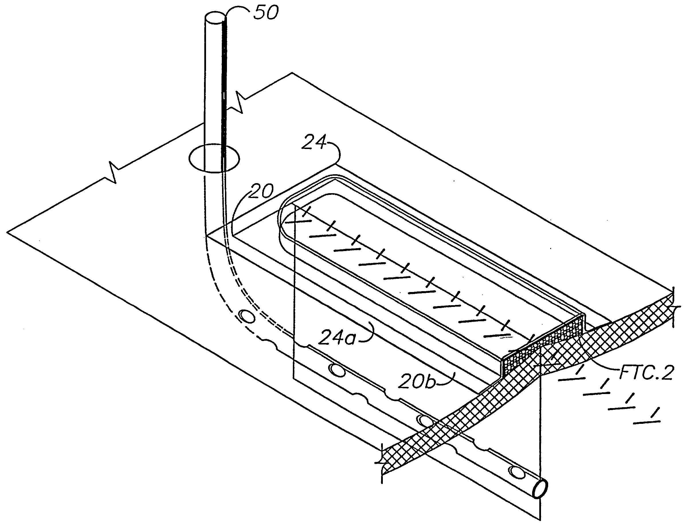
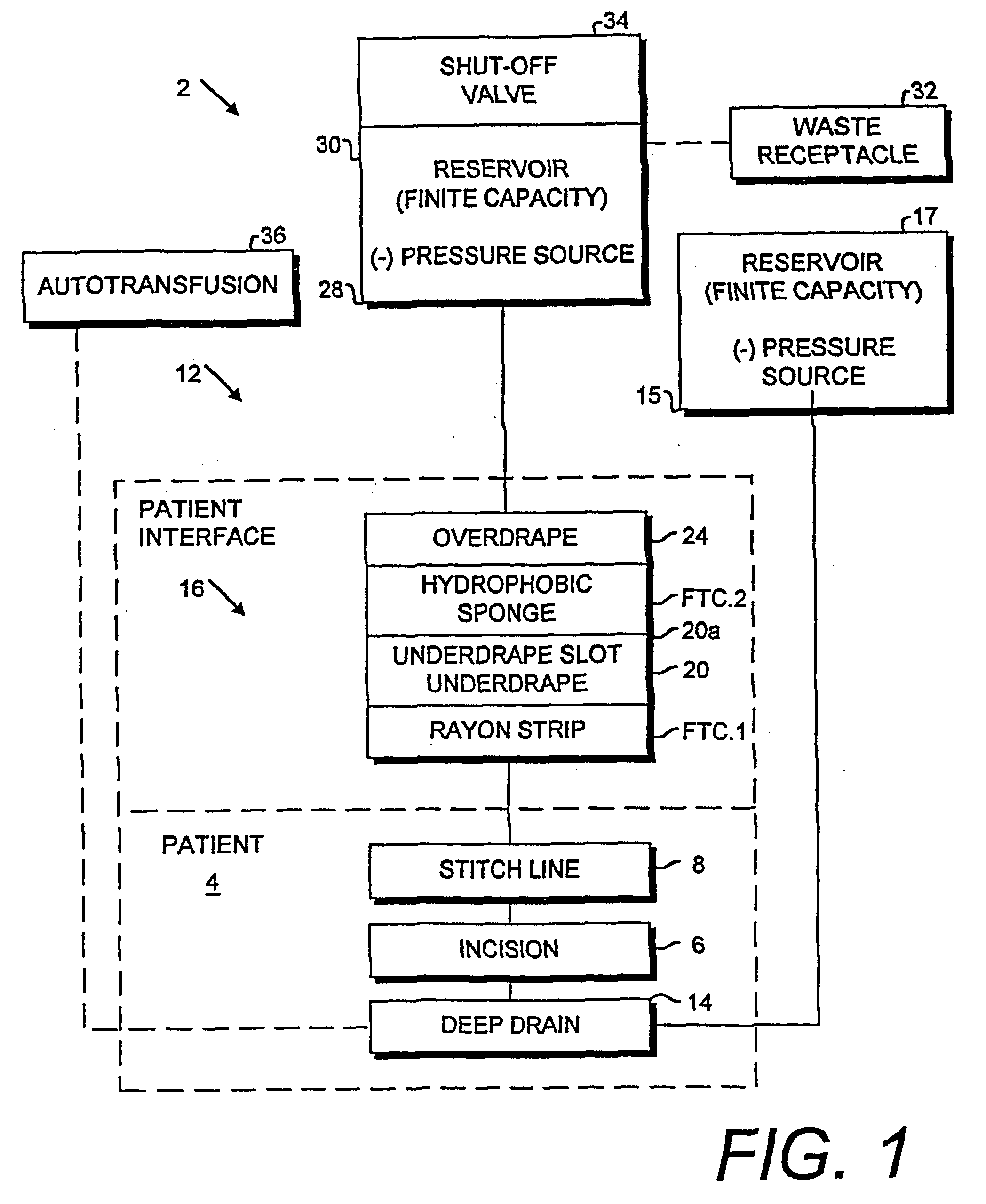
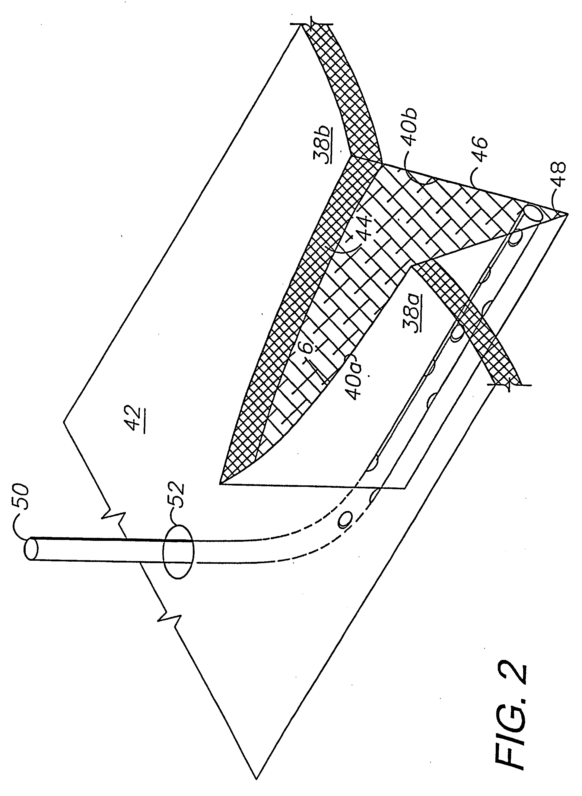
[0020] In the practice of the present invention, a system and method are provided for enhancing closure of separated tissue portions using a surface-applied patient interface. Subsurface drainage, irrigation and autotransfusion components can optionally be used in conjunction with the surface-applied, external interface. The external interface can be advantageously placed over a stitch or staple line and includes a primary transfer component comprising a strip of porous material, such as rayon, applied directly to the patient for wicking or transferring fluid to a secondary transfer component comprising a sponge or foam material. An underdrape is placed between the transfer elements for passing fluid therebetween through an underdrape opening, such as a slot. An overdrape is placed over the secondary transfer component and the surrounding skin surface. The patient interface is connected to a negative pressure source, such as a vacuum assisted closure device, wall suction or a mechanical suction pump. A manual control embodiment utilizes a finite capacity fluid reservoir with a shut-off valve for discontinuing drainage when a predetermined amount of fluid is collected. An automatic control embodiment utilizes a microprocessor, which is adapted for programming to respond to various inputs in controlling the operation of the negative pressure source. A closed wound or incision treatment method of the present invention involves three phases of fluid control activity, which correspond to different stages of the healing process. In a first phase active drainage is handled. In a second phase components can be independently or sequentially disengaged. In a third phase the secondary transfer component can optionally be left in place for protection and to aid in evacuating any residual fluid from the suture / staple line through the primary transfer component.

Problems solved by technology

Tissue separations can result from surgical procedures and other causes, such as traumatic and chronic wounds.
Dead space problems are more apt to occur in the subcutaneous closure.
However, deeper incisions may well require not only skin surface closure, but also time-consuming placement of multiple layers of sutures in the load-bearing planes.
The resulting tissue separations are often subjected to flexure and movement associated with the articulation of the replacement joints.
Although the joints can be immobilized as a treatment option, atrophy and stiffness tend to set in and prolong the rehabilitation period.
For example, arthrotomy, reconstructive and cosmetic procedures, including flaps and scar revisions, also require tissue closures and are often subjected to movement and stretching.
The demands of mobilizing the extremity and the entire patient conflict with the restrictions of currently available methods of external compression and tissue stabilization.
However, many previous fluid-handling procedures and products tended to require additional clean-up steps, expose patients and healthcare professionals to fluid contaminants and require regular dressing changes.
Moreover, insufficient drainage could result in residual blood, exudate and transudate becoming isolated in the tissue planes in proximity to surgical incisions.

Method used


Image

  • Externally-applied patient interface system and method
  • Externally-applied patient interface system and method
  • Externally-applied patient interface system and method

Examples


embodiment dressing assembly 802

XII. Alternative Embodiment Dressing Assembly 802

[0158] A dressing assembly 802 comprising an alternative embodiment of the present invention is shown in FIG. 41 and includes a foam piece 804 in a sheath 806 adapted for opening and closing through a reclosable seal strip 808. The sheath 806 includes an upper drape portion 810, which can comprise a suitable semi-permeable or impervious drape material. The sheath 806 includes a perimeter 812, which can be provided with an optional adhesive perimeter seal 813 adapted for providing a relatively fluid-tight seal around the sheath 806. The perimeter seal 813 can be relatively narrow in order to minimize patient discomfort, skin maceration, etc. A bottom panel 814 comprises a suitable wicking material, such as rayon, and extends to the sheath perimeter 812. The materials comprising the dressing 802 can be chosen for permeability or occlusiveness, biocompatibility, hydrophobic or hydrophilic reaction to liquids, bacteriastatic and antimicro...


PUM


Abstract

A tissue closure treatment system and method are provided with an external patient interface. A first fluid transfer component FTC.1 comprises a strip of porous material, such as rayon, with liquid wicking properties. FTC.1 can be placed directly on a suture line for transferring fluid exuded therethrough. An underdrape is placed over FTC.1 and includes a slot exposing a portion of same. FTC.2 comprises a suitable hydrophobic foam material, such as polyurethane ether, and is placed over the underdrape slot in communication with FTC.1. Negative pressure is applied to FTC.2 through a connecting fluid transfer component FTC.3. A negative pressure source can comprises a manual device or a power-operated suction device. The tissue closure method includes a manual operating mode using a manual suction device with an automatic shut off for discontinuing suction when a predetermined volume of fluid has been drained. An automatic operating mode utilizes a microprocessor, which can be preprogrammed to respond to various patient and operating conditions. The method proceeds through several phases with different components in place and different patient interface functions occurring in each.

Description

CROSS-REFERENCE TO RELATED APPLICATIONS [0001] Continuation-in-part of U.S. patent application Ser. No. 10 / 409,225, filed Apr. 8, 2003, U.S. Pat. No. 6,936,037, which is a continuation-in-part of U.S. patent application Ser. No. 10 / 334,766, filed Dec. 31, 2002, U.S. Pat. No. 6,951,553.BACKGROUND OF THE INVENTION [0002] 1. Field of the Invention [0003] The present invention relates generally to medical devices and methods for treating closed wounds and incisions and for managing moisture therein, and in particular to a system and method for draining and / or irrigating tissue separations, such as surgical incisions, and for compressing and stabilizing a dissected or traumatized field with ambient air pressure created by an external patient interface component and a vacuum source. [0004] 2. Description of the Related Art [0005] Tissue separations can result from surgical procedures and other causes, such as traumatic and chronic wounds. Various medical procedures are employed to close t...

Claims


Application Information

Patent Timeline
Patent Type & Authority Applications(United States)
IPC IPC(8): A61M1/00
CPCA61F13/0203A61M1/0088A61M2205/50A61M2230/00A61M1/0092A61M1/0027A61M1/0025A61M1/0029A61M1/0031A61M1/734A61M1/732A61M1/73A61M1/74A61M1/964A61M1/916A61M1/915A61M1/95A61F13/00068A61F13/0216A61F13/022A61M27/00A61M2205/33
Inventor BUBB, STEPHEN K.ZAMIEROWSKI, DAVID S.
Owner KCI LICENSING INC
Why Eureka
Try Eureka