Light emitting device package and back light unit for liquid crystral display using the same

a technology of light emitting device and liquid crystal display, which is applied in the direction of discharge tube luminescnet screen, lighting and heating apparatus, instruments, etc., can solve the problems of reducing efficiency, exposing a limit in color expression of crystal display, and not being easy to outperform fluorescent light efficiency within a short period of time, so as to increase heat radiation efficiency and prevent device degradation

a technology of light emitting device and liquid crystal display, which is applied in the direction of discharge tube luminescnet screen, lighting and heating apparatus, instruments, etc., can solve the problems of reducing efficiency, exposing a limit in color expression of crystal display, and not being easy to outperform fluorescent light efficiency within a short period of time, so as to increase heat radiation efficiency and prevent device degradation

US20060082271A1Inactive Publication Date: 2006-04-20LG ELECTRONICS INC

Image

  • Light emitting device package and back light unit for liquid crystral display using the same
  • Light emitting device package and back light unit for liquid crystral display using the same
  • Light emitting device package and back light unit for liquid crystral display using the same

Examples


Embodiment Construction

[0030] Preferred embodiments of the present invention will now be described in detail with reference to the accompanying drawings.

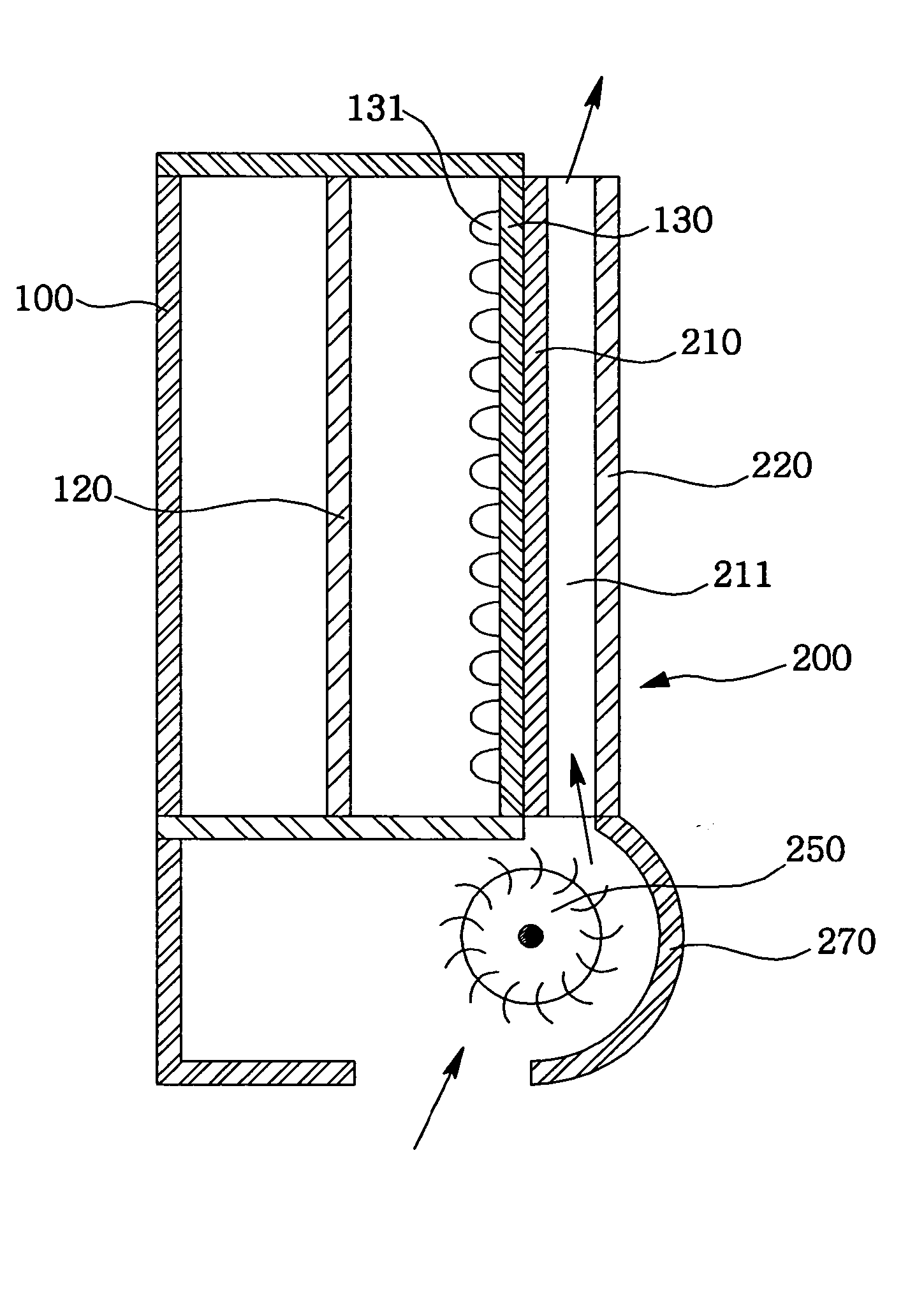
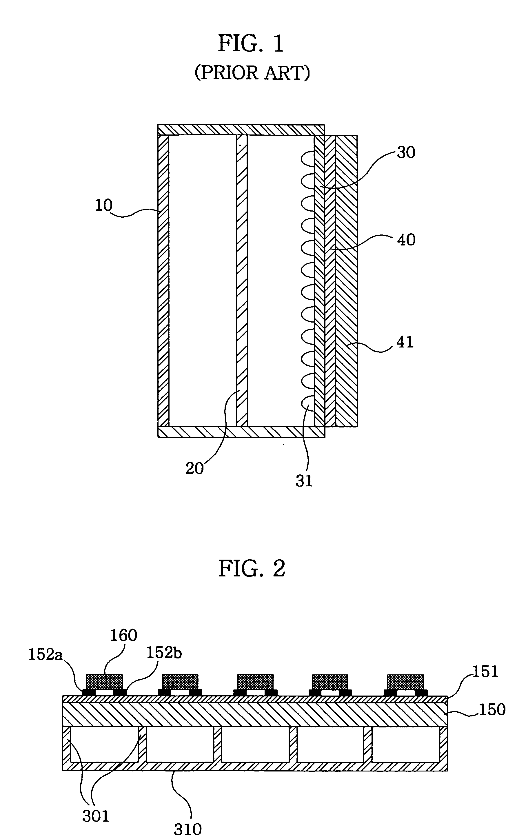
[0031]FIG. 2 is a schematic perspective view of LED package according to the present invention.

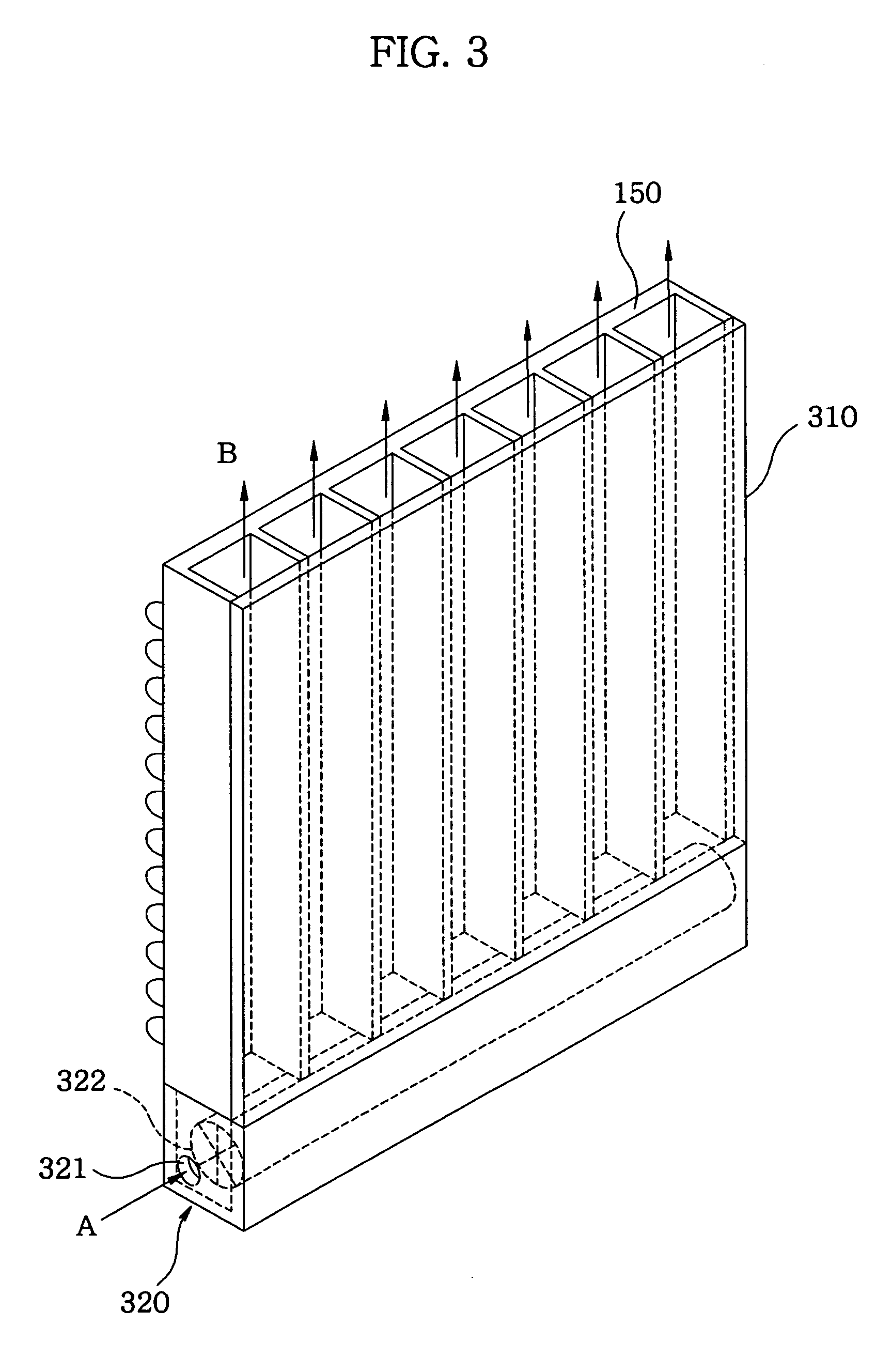
[0032] The LED package comprises: a metal substrate (150); an insulation sheet (151) formed at an upper surface of the metal substrate (150); a plurality of electrode lines (152a. 152b) formed on the insulation sheet (151); LEDs (160) electrically bonded to an upper surface of the plurality of electrode lines (152a. 152b) and arrayed in rows and lines; a plurality of striped protruders (301) fixed at one surface thereof to a lower surface of the metal substrate, each spaced a predetermined distance apart; and a guide member (310) fixed to the other surface of the protruders (301).

[0033] Referring to FIG. 3, the LED package is mounted therein with a fan (322) for sucking air through a suction inlet (321) and is further disposed with a fan case (320) encased th...


PUM


Abstract

A light emitting device package and a back light unit for liquid crystal display using the same wherein a fan is used to forcibly cool an LED package and a back light unit for LCD to increase the heat radiation efficiency and to prevent the degradation of the device.

Description

BACKGROUND OF THE INVENTION [0001] 1. Field of the Invention [0002] The present invention relates to a light emitting device package and a back light unit for liquid crystal display using the same. [0003] 2. Description of the Prior Art [0004] In general, the light emitting diode (LED) is a device for transforming electricity to light by utilizing a theory that, if a current is made to flow in a forward direction in a junction comprising two different semiconductors, electrons and holes are coupled at a junction region to generate a light beam. The said LED has an advantage in that it is resistant to shock, and has an almost eternal life time under a specific condition. [0005] An LED exceeding an incandescent lamp has been currently developed. Furthermore, efforts have been recently waged to use an LED of high efficiency as a lighting apparatus. However, the said LED does not match the efficiency of fluorescent light and it does not seem to be that easy to outperform the efficiency ...

Claims


Application Information

Patent Timeline
20 Apr 2006
Publication
US20060082271A1
IPC
H05B33/00; H01J61/52; H01K1/58; H01J7/26; F21V29/02; H01L33/44; H01L33/62; H01L33/64
CPC
F21V29/02; F21Y2101/02; F21V29/74; G02F2001/133628; G02F1/133603; F21Y2115/10; G02F1/133628; G02F1/1335
Inventors
LEE, SEUNG MIN; JANG, JUN HO