Compressor and hermetic housing with minimal housing ports

a compressor and hermetic housing technology, applied in the direction of machines/engines, positive displacement liquid engines, lighting and heating apparatus, etc., can solve the problems of increasing the cost of the compressor and the number of locations on the compressor housing at which fluid leakage could potentially occur, so as to reduce the cost of the compressor and simplify the manufacture of the compressor assembly. , the effect of reducing the initial cos

Inactive Publication Date: 2006-04-20
TECUMSEH PROD CO
View PDF18 Cites 31 Cited by
  • Summary
  • Abstract
  • Description
  • Claims
  • Application Information

AI Technical Summary

Benefits of technology

[0015] An advantage of the present invention is that same provides a multi-stage compressor mechanism wherein intermediate pressure refrigerant may be cooled without requiring an intercooler and the two housing ports associated with the use of an intercooler. The elimination of the intercooler is beneficial because it may simplify the manufacture of the compressor assembly.
[0016] The reduction in the number of ports required in the hermetically sealed housing is also beneficial because each of the ports of the housing must be properly sealed to ensure that the housing provides a hermetically sealed enclosure and an increase in the number of ports in the housing increases the chances that one of such ports may later develop a leak and may also increase the initial cost of manufacturing the compressor assembly.

Problems solved by technology

A problem with the foregoing compressor mechanism is that the compressor housing requires as many as four or more ports, each of which include an opening in the compressor housing which requires a seal, thereby increasing the cost of the compressor and the number of locations on the compressor housing at which a fluid leak could potentially occur.

Method used


Image

  • Compressor and hermetic housing with minimal housing ports
  • Compressor and hermetic housing with minimal housing ports
  • Compressor and hermetic housing with minimal housing ports

Examples


Embodiment Construction

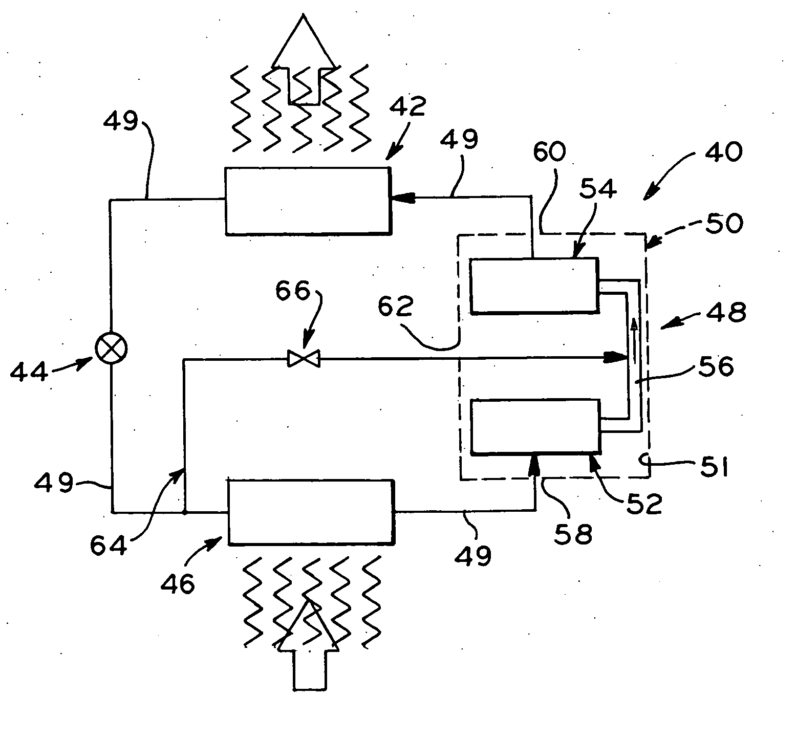
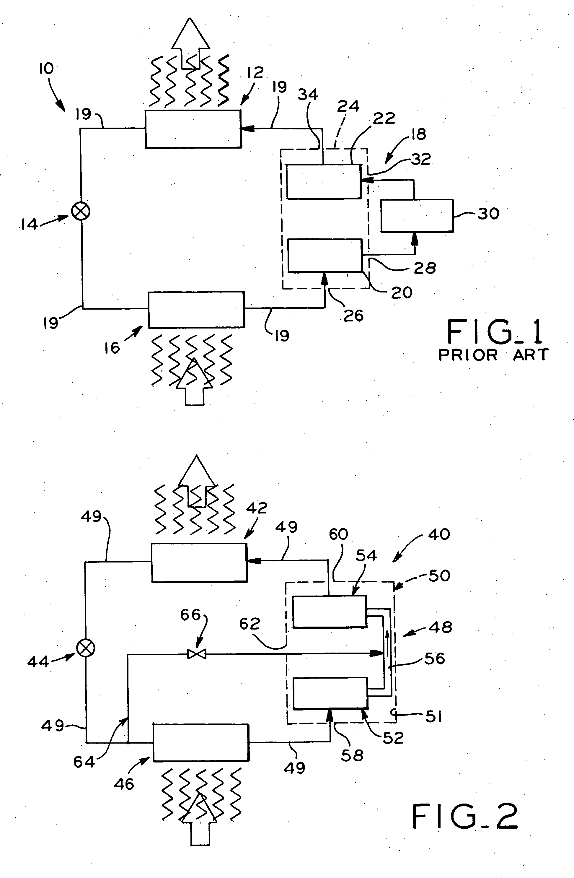
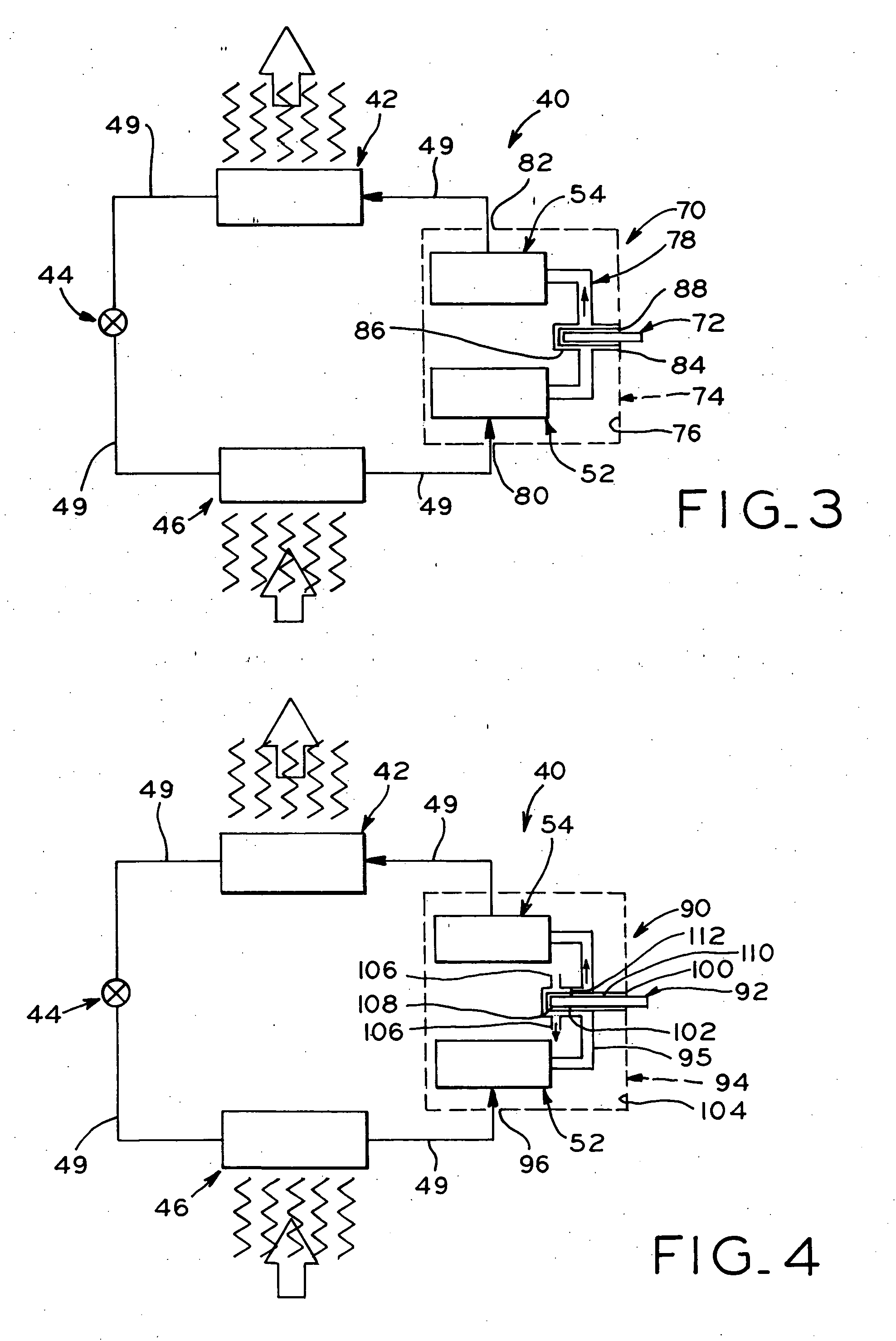
[0023] Referring to FIG. 2, vapor compression system 40 is a closed loop fluid circuit through which a working fluid is circulated. Vapor compression system 40 has operably disposed therein, in serial order, first heat exchanger 42, expansion device 44, second heat exchanger 46, and compressor assembly 48. In the illustrated vapor compression system 40, the working fluid is carbon dioxide and vapor compression system 40 is a transcritical system. Consequently, first heat exchanger 42 is a gas cooler wherein the carbon dioxide within gas cooler 42 is at a supercritical pressure while the carbon dioxide within second heat exchanger or evaporator 46 is at a subcritical pressure. The components of vapor compression system 40 are fluidly connected by a plurality of conduits 49. Although a charge of carbon dioxide flows through the fluid circuit in the illustrated embodiments, other refrigerants may alternatively be employed with the present invention.

[0024] The use of carbon dioxide as ...


PUM


Abstract

A vapor compression system having a multi-stage compressor with a minimal number of ports located in the hermetically sealed compressor housing. A working fluid at suction pressure enters the compressor housing through a first port and is compressed to an intermediate pressure. The intermediate pressure refrigerant flows from the first stage compressor mechanism to the second stage compressor mechanism where it is compressed to a discharge pressure and discharged through a second port. The intermediate pressure refrigerant is in thermal communication with a heat exchange medium which is introduced into the compressor housing through a third port in the housing.

Description

BACKGROUND OF THE INVENTION [0001] 1. Field of the Invention [0002] The present invention relates to a hermetically sealed compressor for a vapor compression system and, more particularly, to a compressor housing having a minimal number of housing ports. [0003] 2. Description of the Related Art [0004] A vapor compression system typically includes at least a compressor, a first heat exchanger, an expansion device, and a second heat exchanger fluidly linked in serial order. Other components such as accumulators, flash tanks, and the like are also well-known and may be employed with the vapor compression system, but are not essential for the operation of the vapor compression system. [0005] One known type of vapor compression system is a transcritical vapor compression system wherein the refrigerant is compressed to a supercritical pressure and is returned to the compressor at a subcritical pressure. When the refrigerant is at a supercritical pressure, the liquid and vapor phases of th...

Claims


Application Information

Patent Timeline
Patent Type & Authority Applications(United States)
IPC IPC(8): F04B3/00F04B5/00
CPCF04B3/00F04B25/00F25B1/10F25B2309/061
Inventor MANOLE, DAN M.
Owner TECUMSEH PROD CO
Why Eureka
Try Eureka