
Magnet and coil configurations for MRI probes

a magnetic resonance imaging and coil configuration technology, applied in the field of nuclear magnetic resonance probes, can solve the problems of large and expensive equipment that is not very mobile, the conventional mri (magnetic resonance imaging) system suffers from a number of limitations, and the acquisition time is rather long, so as to achieve high saturation flux density, high permeability material, and magnetic field

Inactive Publication Date: 2006-04-20
TOPSPIN MEDICAL ISRAEL
View PDF65 Cites 50 Cited by
  • Summary
  • Abstract
  • Description
  • Claims
  • Application Information

AI Technical Summary

Benefits of technology

[0017] In another example, there are a plurality of magnets arranged axially along the probe. Each magnet is magnetized in a direction perpendicular to the z-axis, but in a different direction in the x-y plane that differs by less than 180 degrees from the direction of magnetization of the next magnet. For example, there are four magnets, magnetized respectively in the +x direction, the +y direction, the −x direction, and the −y direction. Each of these magnets has its own RF coil, and is used to obtain imaging data from a different azimuthal direction. Since all four magnets can produce data simultaneously, there is no need to take data first in one azimuthal direction, then rotate the probe, then take data in another azimuthal direction, etc., and a complete scan can be done more quickly. Even if the data from all the different magnets is not obtained simultaneously, but some or all of it is obtained sequentially, for example to avoid interference between magnets, this probe configuration still saves time because it is not necessary to rotate the probe. It also provides greater accuracy, because the difference in azimuthal direction between the different magnets is fixed by the structure of the probe, while in a probe which must be rotated, there may be an error in the angle of rotation.
[0030] An aspect of some embodiments of the invention concerns an active protection circuit with very high bandwidth. The protection circuit isolates a sensitive low noise amplifies used to amplify weak received NMR signals, from an RF antenna, when the antenna is transmitting high power RF pulses. The same RF antenna can thus be used for both receiving and transmitting. The protection circuit uses active elements, such as toroid protectors, and optionally also uses passive elements such as a high pass filter and Schottky diodes. The circuit has a very high bandwidth and short ringing time, allowing the amplifier to have a very short dead time, as short as a few microseconds.

Problems solved by technology

Conventional MRI (magnetic resonance imaging) systems suffer from a number of limitations.
They require highly homogeneous magnetic fields, which, for imaging a large volume such as the human body, generally means large and expensive equipment that is not very mobile.
The distance between the imaged volume and the RF antenna means that a rather long acquisition time is needed to obtain a reasonable signal to noise ratio at high resolution.
Because most patients cannot tolerate being inside the narrow bore of a large magnet for more than a few minutes, the images have limited resolution, typically about 1 millimeter.
While “open” MRI magnets exist, with less claustrophobic bores, they have lower magnetic fields which further reduces the signal to noise ratio, so these systems also typically have resolution no better than 1 mm.
One problem in “inside out” medical MRI, is that a high magnetic field gradient is generally produced outside the magnet.
If the bandwidth is made wider, then the noise increases.

Method used


Image

  • Magnet and coil configurations for MRI probes
  • Magnet and coil configurations for MRI probes
  • Magnet and coil configurations for MRI probes

Examples


Embodiment Construction

MRI Probe with Obliquely Magnetized Magnets

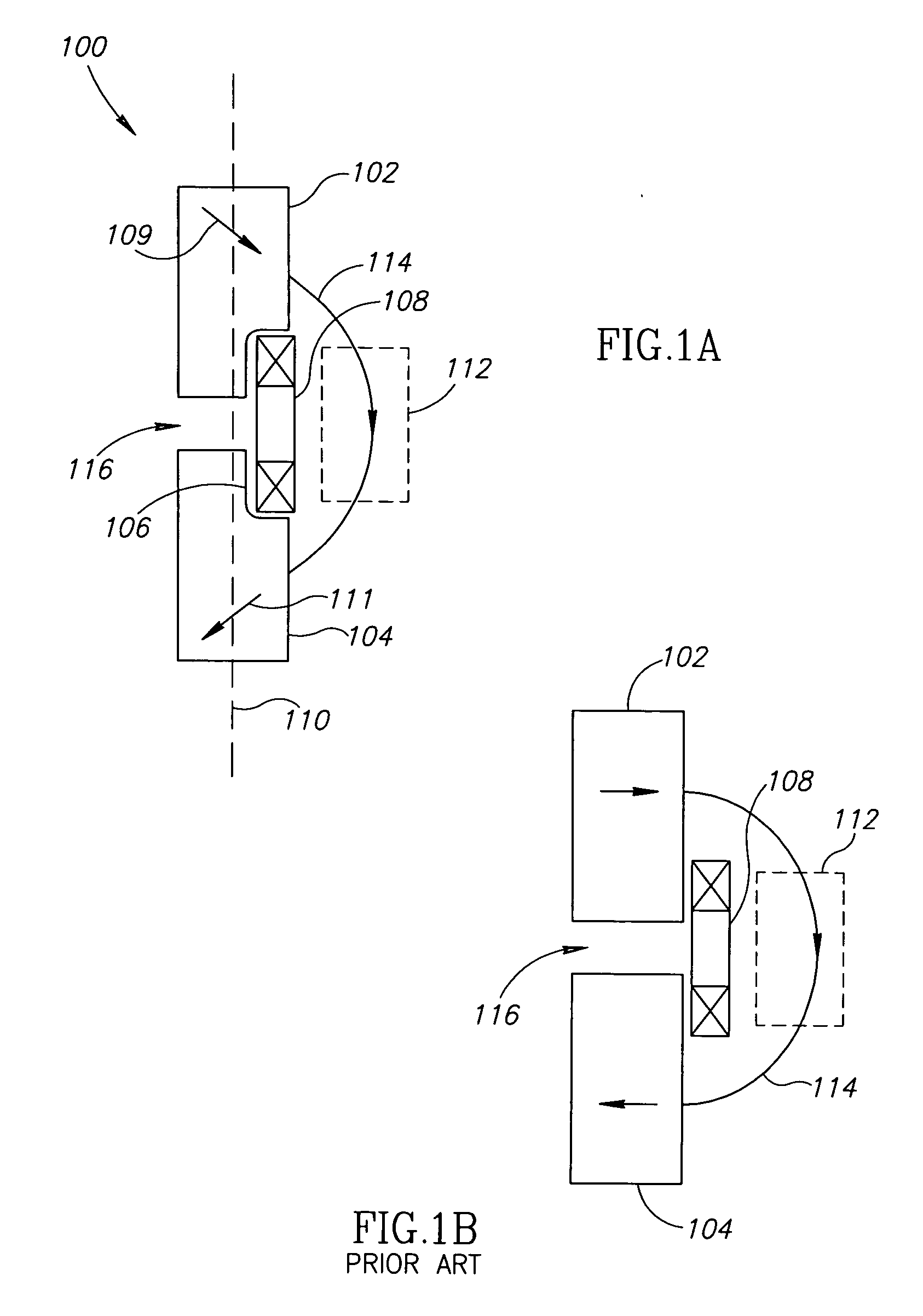
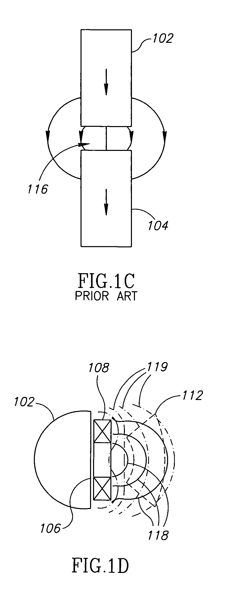
[0183]FIG. 1A shows a side-view (x-z plane) cross-section of an MRI probe 100, with magnets 102 and 104. Except for a slot 106, where an RF coil 108 is optionally located, the magnets are circular cylinders, with longitudinal axis (z-axis) 110. RF coil 108, or any of the RF coils shown in the other drawings, is optionally both a transmitting and receiving coil. Alternatively, there are separate transmitting and receiving coils, one or both of them optionally located in slot 106 in the case of probe 100. Optionally, RF coil 108, or an RF coil in any of the other drawings, or one or both of the separate transmitting and receiving coils, is replaced by a different kind of RF antenna. Perspective views of probe 100 are shown in FIGS. 13A and 13B.

[0184] This probe is similar to that described by Blank et al, in U.S. Pat. No. 6,704,594, except for the direction of magnetization of the magnets, indicated in FIG. 1A by arrows 109 and 111 on the ma...


PUM


Abstract

A probe, with a longitudinal axis, for use in an NMR system, the probe comprising: (a) a plurality of static magnetic field sources which create a static magnetic field that is non-axisymmetric about the longitudinal axis, in a region outside the probe; and (b) at least one antenna, compromising one or more antennas together capable of creating a time-varying magnetic field which is capable of exciting nuclei in a sub-region of the region, and capable of receiving NMR signals from said excited nuclei and generating NMR electrical signals therefrom; wherein the plurality of magnetic field sources comprise adjacent static magnetic field sources that are magnetized in directions that differ by more than 10 degrees and less than 170 degrees.

Description

RELATED APPLICATIONS [0001] This application is related to a patent application titled “Expanding MRI Probe,” attorney's docket number 334 / 03529, filed on even date, at the US Patent and Trademark Office, the disclosure of which is incorporated herein by reference. FIELD OF THE INVENTION [0002] The field of the invention is nuclear magnetic resonance probes. BACKGROUND OF THE INVENTION Problems with Conventional MRI [0003] Conventional MRI (magnetic resonance imaging) systems suffer from a number of limitations. They require highly homogeneous magnetic fields, which, for imaging a large volume such as the human body, generally means large and expensive equipment that is not very mobile. The distance between the imaged volume and the RF antenna means that a rather long acquisition time is needed to obtain a reasonable signal to noise ratio at high resolution. Because most patients cannot tolerate being inside the narrow bore of a large magnet for more than a few minutes, the images ...

Claims


Application Information

Patent Timeline
IPC IPC(8): A61B5/05A61B6/00A61M25/00
CPCA61B5/02007A61B5/055G01R33/285G01R33/287G01R33/3808G01R33/383
Inventor BLANK, AHARONLEWKONYA, GADIZUR, YUVALFRIEDMAN, HANNATIDHAR, GIL
Owner TOPSPIN MEDICAL ISRAEL
Learn More