
Composition for the removing of sidewall residues

Active Publication Date: 2006-04-27
BASF AG
View PDF9 Cites 5 Cited by
  • Summary
  • Abstract
  • Description
  • Claims
  • Application Information

AI Technical Summary

Benefits of technology

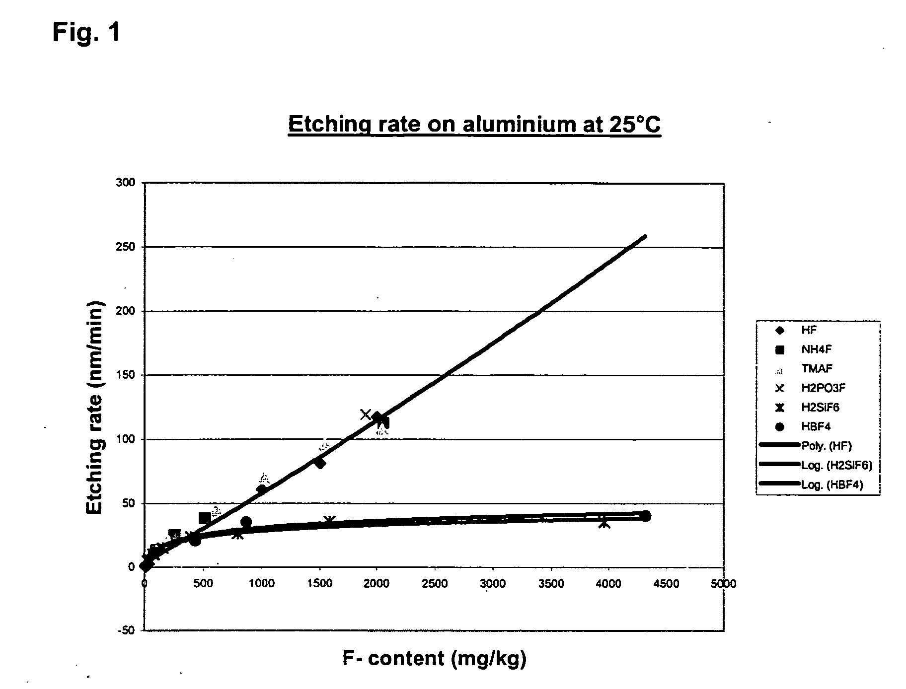
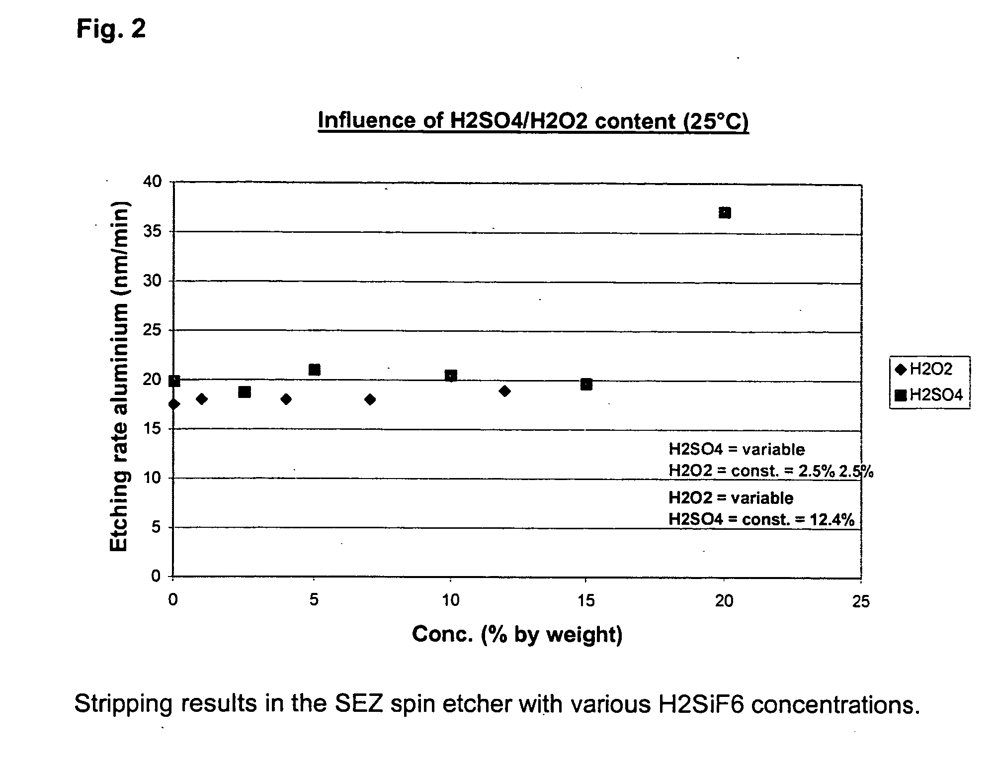
[0018] The object of the present invention consists in providing a stable composition or stripper solution for the removal of residual polymers, so-called “sidewall residues”, which gives stable etching rates on aluminium or aluminium / copper alloys in a great concentration range of the additive, and completely removes the residual polymers described above without damaging the metallisation layers or conductor tracks or causing corrosion.

Problems solved by technology

Dilute sulfuric acid / hydrogen peroxide solutions (DSP) on their own are not sufficient for the removal of the residual polymers and therefore comprise additional additives.
The disadvantage in the use of hydrofluoric acid as etching additive consists in that the concentration must be maintained and monitored very accurately.
An excessively high concentration would attack the metal surface excessively, while an inadequate hydrofluoric acid concentration does not achieve an adequate cleaning action.
In particular, the very low concentration of the solutions for use in tank units makes process control very complex.
This aim can only be achieved by continuous, precise measurement and controlled replenishment of hydrofluoric acid.

Method used


Image

  • Composition for the removing of sidewall residues
  • Composition for the removing of sidewall residues
  • Composition for the removing of sidewall residues

Examples


example 1

[0045] Etched wafers having the layer structure described above were processed in the SEZ spin etcher. This technology is a single-wafer process in which the wafer lying horizontally in a process chamber is set in rotation and impinged on by the etching liquid via a nozzle. In the process, the nozzle arm moves horizontally to and fro over the wafer surface. The etching process is followed by a rinsing process with ultrapure water in accordance with the same principle. For drying, the wafer is finally blown dry with N2 at a high rotational speed.

[0046] Step 1: Stripping

[0047] Composition of the mixture:

Sulfuric acid:12.0% by weightHydrogen peroxide: 2.4% by weightH2SiF6:500 mg / kg

[0048] 600 rpm, 1 l / min through-flow, 25° C., 30 sec.

[0049] Step 2: Rinsing with Ultrapure Water

[0050] 600 rpm, 1 l / min through-flow, 25° C., 30 sec.

[0051] Step 3: Spin Drying with Blowing off by N2

[0052] 2000 rpm, 150 l / min.

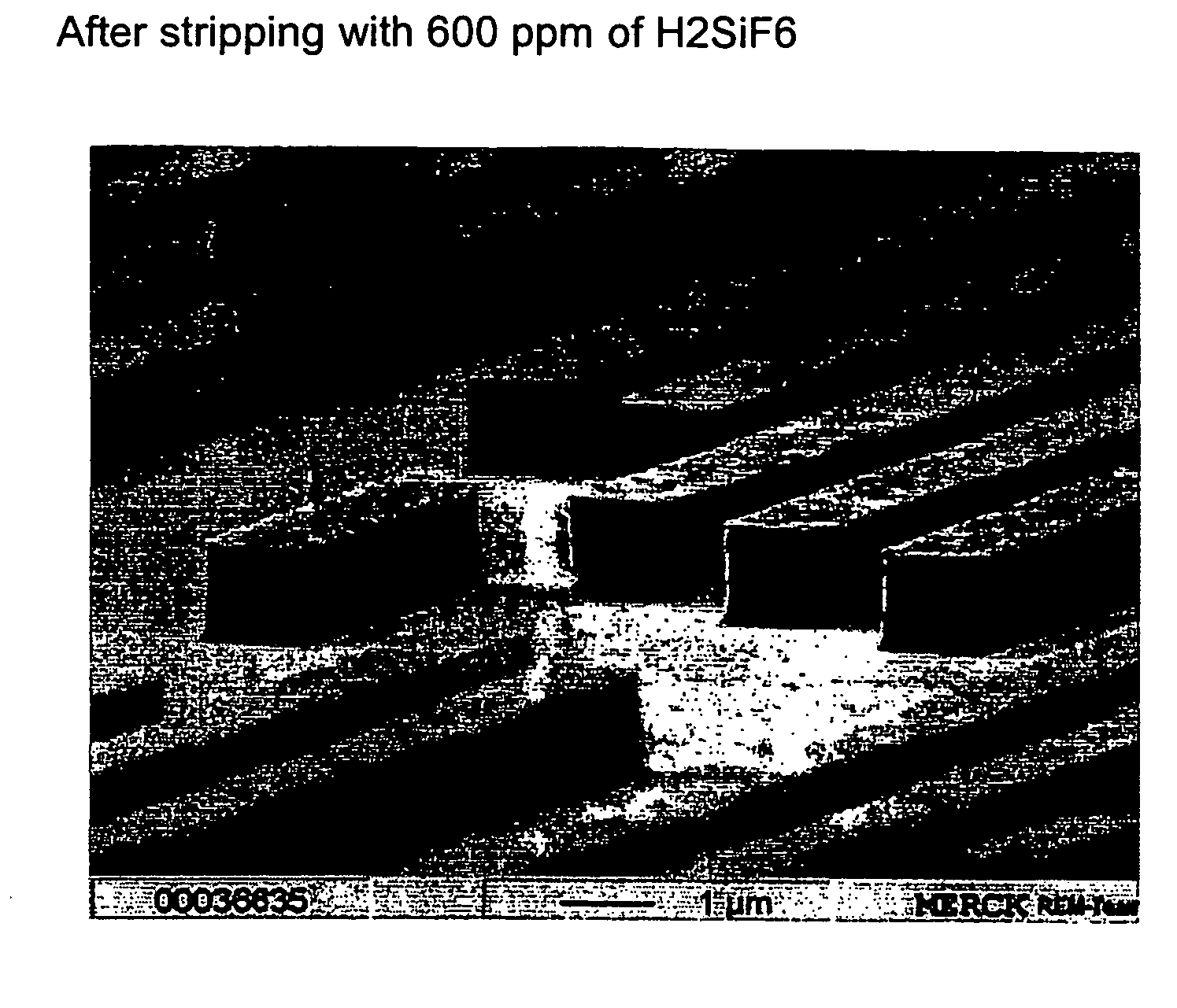
[0053]FIG. 3 shows the fully cleaned surface, without attack of the metallis...

example 2

[0054] The same wafers as in Example 1 were processed in a Mattson AWP200 tank unit.

[0055] Step 1: Stripping

[0056] Composition of the mixture:

Sulfuric acid:12.0% by weightHydrogen peroxide: 2.4% by weightH2SiF6:100 mg / kg

[0057] 15 l / min. recirculation, 25 ° C., 45 s

[0058] Step 2: Rinsing with Ultrapure Water

[0059] 35 l / min through-flow, 25° C., 10 min.

[0060] Step 3: Marangoni Dryer

[0061]FIG. 3 shows the fully cleaned surface, without attack on the metallisation.

example 3

[0062] The same wafers as in Example 1 were processed in a beaker. For better characterisation of the stripping process, wafers with very thick polymer layers were used.

[0063] Step 1: Stripping

[0064] Composition of the mixture:

Sulfuric acid: 12% by weightHydrogen peroxide:2.4% by weightH2SiF6:100 mg / kgOenanthic acid: 80 mg / kg

[0065] 100 rpm. 25° C., 60 sec.

[0066] Step 2: Rinsing with Ultrapure Water in the Beaker

[0067] 25° C., 5 min.

[0068] Step 3: Drying in the Nitrogen Oven

[0069] 100° C., 10 min

[0070] It can be seen in FIG. 12 that the polymers have been removed apart from a thin residual layer.


PUM

PropertyMeasurementUnit
Temperatureaaaaaaaaaa
Fractionaaaaaaaaaa
Fractionaaaaaaaaaa

Abstract

The present invention relates to a composition for the removal of so-called “sidewall residues” from metal surfaces, in particular from aluminium or aluminium-containing surfaces, in particular from aluminium or aluminium-containing surfaces, during the production of semiconductor elements.

Description

[0001] The present invention relates to a composition for the removal of so-called “sidewall residues” from metal surfaces, in particular from aluminium or aluminium-containing surfaces, during the production of semiconductor elements. PRIOR ART [0002] Conductor tracks in integrated circuits consist principally of aluminium or an aluminium / copper alloy (0.5% of copper), which is deposited over the entire surface by sputtering. The structures are subsequently formed by coating with photoresist, exposure and development. In the subsequent dry-etching process, the aluminium is structured, during which polymers form, inter alia, from constituents of the photoresist and the etching gases and deposit as a continuous layer predominantly on the sidewalls of the aluminium conductor tracks. Even after removal of the photoresist by means of oxygen plasma or Caro's acid, these polymers remain on the conductor tracks. These so-called residual polymers, which are generally known as “sidewall resi...

Claims


Application Information

Patent Timeline
IPC IPC(8): B08B6/00H01L21/3065C11D3/39C11D7/08C11D11/00G03F7/42H01L21/02H01L21/304H01L21/3213H01L21/768H01L25/00
CPCC11D3/3947C11D7/08Y10S438/963G03F7/423H01L21/02071C11D11/0047C11D2111/22G03F7/42
Inventor MELLIES, RAIMUNDBOERNER, MARCARNOLD, LUCIABARKO, ANDREARHEIN, RUDOLF
Owner BASF AG
Learn More