
Plating apparatus and plating method

a technology of plating apparatus and plating film, which is applied in the direction of sealing devices, manufacturing tools, electric circuits, etc., can solve the problems and difficulty in forming a plated film of more uniform thickness, so as to achieve the effect of increasing the cost of the plating apparatus and low cos

Inactive Publication Date: 2006-04-27
EBARA CORP +1
View PDF5 Cites 37 Cited by
  • Summary
  • Abstract
  • Description
  • Claims
  • Application Information

AI Technical Summary

Benefits of technology

[0013] The method of stopping plating when the plating time has reached a predetermined time and the method of stopping plating when the integrated quantity of electricity has reached a predetermined value have the advantage of being simple and low cost. When using these methods in a so-called flattening plating which is employed for forming interconnects by, for example, the above-described damascene technique, however, a larger amount of plating than the necessary plating amount must be applied to a substrate because of the necessity of taking account of process variation. The method using a film-thickness monitor involves the use of a generally expensive monitor, leading to an increased cost of the plating apparatus.

Problems solved by technology

When using these methods in a so-called flattening plating which is employed for forming interconnects by, for example, the above-described damascene technique, however, a larger amount of plating than the necessary plating amount must be applied to a substrate because of the necessity of taking account of process variation.
The method using a film-thickness monitor involves the use of a generally expensive monitor, leading to an increased cost of the plating apparatus.
Therefore, it is considered difficult to form a plated film of more uniform thickness over the entire surface to be plated of the substrate with fine interconnect recesses formed therein, only by using the split anodes, and also to reliably embed the plated metal within the fine recesses without forming voids therein.

Method used


Image

  • Plating apparatus and plating method
  • Plating apparatus and plating method
  • Plating apparatus and plating method

Examples


Embodiment Construction

[0112] Preferred embodiments of the present invention will be described below with reference to the drawings. The following embodiments relate to the application of the present invention useful for forming interconnects of copper by embedding copper as an interconnect material in fine recesses for interconnects formed in a surface of the substrate. However, it should be noted that other kinds of interconnect materials may be used instead of copper.

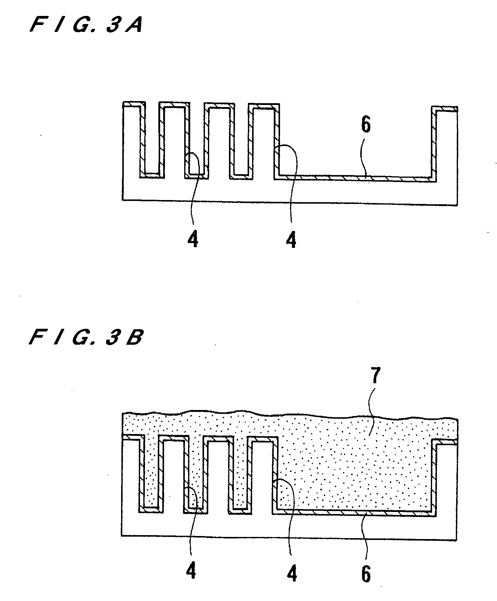
[0113]FIGS. 4A through 4D illustrate an example of forming copper interconnects in a semiconductor device. As shown in FIG. 4A, an insulating film 2, such as an oxide film of SiO2 or a film of low-k material, is deposited on a conductive layer 1a formed on a semiconductor base 1 having formed semiconductor devices. Via holes 3 and trenches 4 are formed in the insulating film 2 by performing a lithography / etching technique so as to provide fine recesses for interconnects. Thereafter, a barrier layer 5 of TaN or the like is formed on the in...


PUM

PropertyMeasurementUnit
thicknessaaaaaaaaaa
thicknessaaaaaaaaaa
thicknessaaaaaaaaaa

Abstract

A plating apparatus can securely carry out a flattening plating of a substrate to form a plated film having a flat surface without using a costly mechanism, and without applying an extra plating to the substrate. The plating apparatus includes a substrate holder; a cathode section having a seal member for watertightly sealing a peripheral portion of the substrate, and a cathode electrode for supplying an electric current to the substrate; an anode disposed in a position facing the surface of the substrate; a porous member disposed between the anode and the surface of the substrate; a constant-voltage control section for controlling a voltage applied between the cathode electrode and the anode at a constant value; and a current monitor section for monitoring an electric current flowing between the cathode electrode and the anode, and feeding back a detection signal to the constant-voltage control section.

Description

BACKGROUND OF THE INVENTION [0001] 1. Field of the Invention [0002] The present invention relates to a plating apparatus and a plating method, and more particularly to a plating apparatus and a plating method useful for forming interconnects by filling a conductive metal (interconnect material) such as copper (Cu) into fine interconnect patterns (recesses) formed in a substrate such as a semiconductor substrate. [0003] 2. Description of the Related Art [0004] In recent years, instead of using aluminum or aluminum alloys as a material for forming interconnect circuits on a semiconductor substrate, there is an eminent movement towards using copper (Cu) that has a low electric resistivity and high electromigration resistance. Copper interconnects are generally formed by forming fine recesses for interconnects, such as trenches or via holes in a circuit form, in a semiconductor substrate, embedding the fine recesses with copper (interconnect material) by copper plating, and removing a c...

Claims


Application Information

Patent Timeline
Patent Type & Authority Applications(United States)
IPC IPC(8): C25D21/12C25B15/00
CPCC25D5/22C25D17/12C25D21/12H01L21/2885H01L21/7684H01L21/76849H01L21/76877C25D7/123C25D5/18C25D17/001C25D17/002C25D17/005C25D17/004C25D5/611
Inventor KURASHINA, KEIICHINAGAI, MIZUKIYAMAMOTO, SATORUKANDA, HIROYUKIMISHIMA, KOJIMORISAWA, SHINYAKUNISAWA, JUNJIIDE, KUNIHITOSUZUKI, HIDENAOCOOPER, EMANUELVEREECKEN, PHILIPPEBAKER-O' NEAL, BRETTDELIGIANNI, HARIKLIA
Owner EBARA CORP
Learn More