Sealing device for maxi rotary cylinder

Inactive Publication Date: 2006-04-27
SAKAKIBARA KOUICHI
View PDF9 Cites 2 Cited by
  • Summary
  • Abstract
  • Description
  • Claims
  • Application Information

AI Technical Summary

Benefits of technology

[0005] It is an object of the invention to provide a sealing device for a maxi rotary cylinder that withstands higher temperatures and a greater amount of axial movement with the maximum sealing effectiveness at a small cost and minimizes degeneration with no maintenance. On the contrary, the above-mentioned labyrinth seals, various kinds of band seals or even the combinations of them don't have enough sealing effectiveness. Besides, the seals near the inner part of the rotary two-tier cylinder and the combustion chamber are in higher temperatures for combustion, carbonization, calcinations, and so on to prevent pollution by dioxin, etc. recently. Moreover, concerning contemporary larger-sized cylinders, formation of a true circle is very difficult. Therefore, conventional seals degenerate easily because of higher temperatures and a greater amount of axial movement with transformation by the weight.

Problems solved by technology

On the contrary, the above-mentioned labyrinth seals, various kinds of band seals or even the combinations of them don't have enough sealing effectiveness.
Moreover, concerning contemporary larger-sized cylinders, formation of a true circle is very difficult.
Therefore, conventional seals degenerate easily because of higher temperatures and a greater amount of axial movement with transformation by the weight.

Method used


Image

  • Sealing device for maxi rotary cylinder
  • Sealing device for maxi rotary cylinder
  • Sealing device for maxi rotary cylinder

Examples


first embodiment

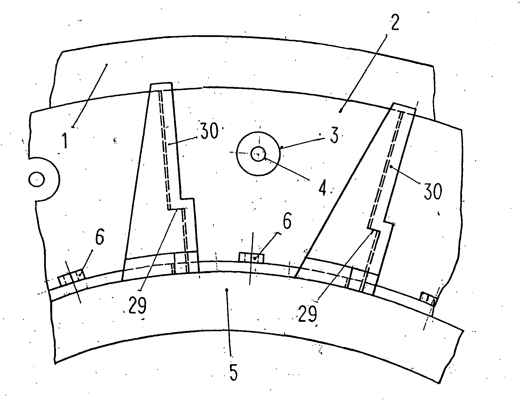
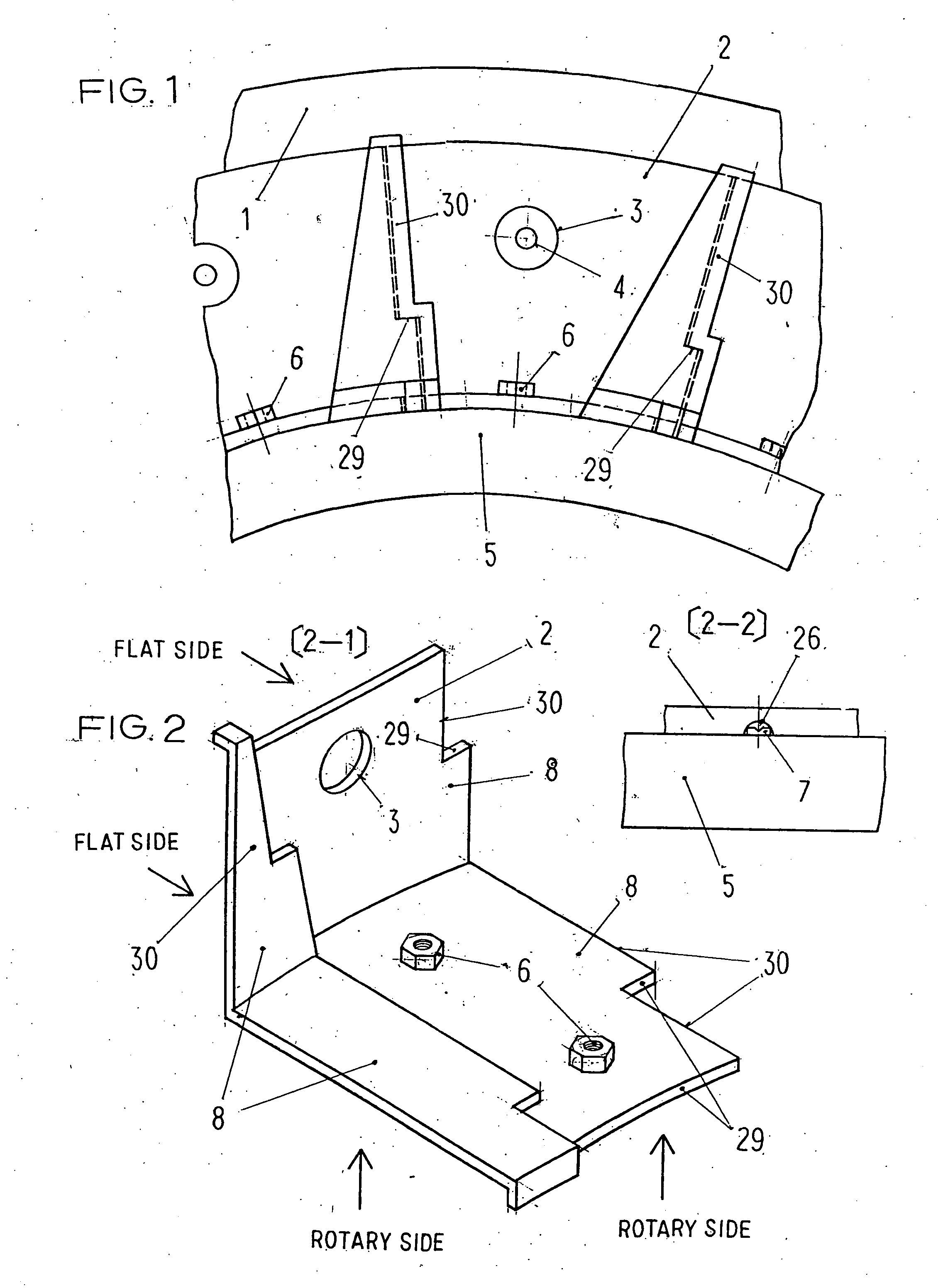
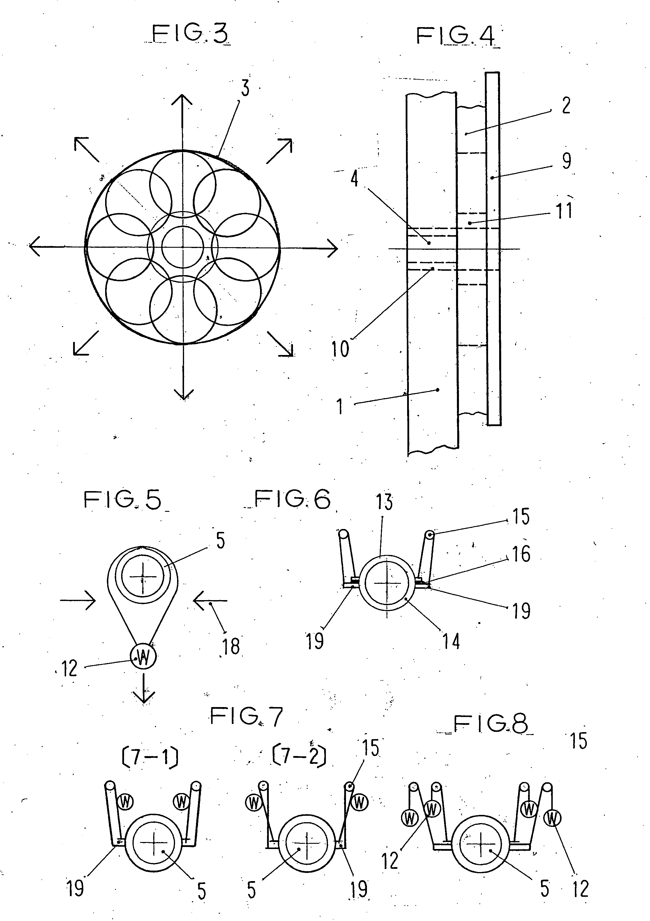
[0065] Referring to FIG. 1, a sealing device according to a first embodiment of the invention has a plurality of L-shaped seals (2) each of which has one round surface and the other flat surface contacted on the cylinder (5) and on the fixed shell (1) respectively at the intersection. The seal is fitted by a slide (with a bolt) in a hole (FIG. 1(4) and FIG. 4 (4)) on the fixed shell. The seal has balanced slide bushes (FIG. 4 (11)) to slide up and down, etc. smoothly and the seal is bolted on the seal-pressing plate (FIG. 4 (9)). Basically, the bush is as thick as the seal, but the thickness of the bush is adjusted for a slide. Then, the plural- (three-) dimensional sealing surfaces (FIG. 2 (8)) of one seal are crossed into the sealing surfaces of another seal with nuts of joint metals (FIG. 1, FIG. 2 (6)) and joint metals (FIG. 9 (9-1)) for a circumference or plural circumferences of the cylinder, if necessary. The seals may be crossed freely and tightly with a circle of flexible w...

second embodiment

[0069] As shown in FIG. 2 (2-2), the second embodiment of the sealing device incorporates elastic sealing material on the sealing surface, which can seal air more effectively than the first embodiment. The above-mentioned sealing uses the general natural pressure of the sealing, while the sealing in FIG. 12 uses a bolt-adjustment type and the sealing in FIG. 13 uses a type with measures for tension (an automatic adjustment together with spring pressure).

third embodiment

[0070] A sealing device according to the third embodiment provides not manual but automatic measures for tension as mentioned afore, generally at one or more-halfway cross sections so that the seals could be always contacted very tightly on the cylinder. Instead of this spring in high temperatures, as mentioned afore, a weight for sealing is fitted at the bottom of one ring of dual rings out of a chain or a wire on the circumference of the cylinder. To contact more tightly on the cylinder, both of them may be used.


PUM


Abstract

A sealing device has a plurality of L-shaped seals each of which has one round surface and the other flat surface contacted on outer sidewall of the powered rotary cylinder and on outer sidewall of the shell respectively at the intersection. One L-shaped seal is crossed into another L-shaped seal on the sides. The L-shaped seal with a hole on the flat surface is fitted by a slide on the fixed shell. The seals crossed freely on these three-dimensional sealing surfaces (with measures for tension) are arranged in a circumferential direction of the cylinder.

Description

BACKGROUND OF THE INVENTION [0001] 1. Field of the Invention [0002] This invention relates to a sealing device for a maxi rotary cylinder such as a rotary kiln, a rotary cooler and a rotary drier, etc. used in industrial waste destruction, limestone-, alumina-, coke-, cement-, carbide-making, and the like. The sealing device is attached to a one- or two-tier cylinder and fixed shell (housing) to seal air, gas, and so on. [0003] 2. Description of the Related Art [0004] Conventionally, a variety of air (gas) seals such as labyrinth seals, band seals, band seals with packing, seals for dividing spring pressure and the combinations of them are used for a rotary kiln and fixed shell (housing) in cement calcinations, paper sludge, and so on. They are suggested in official patent reports and other things. BRIEF SUMMARY OF THE INVENTION [0005] It is an object of the invention to provide a sealing device for a maxi rotary cylinder that withstands higher temperatures and a greater amount of a...

Claims


Application Information

Patent Timeline
IPC IPC(8): F16J15/02F16J15/16F27B7/24
CPCF27B7/24
Inventor SAKAKIBARA, KOUICHI
Owner SAKAKIBARA KOUICHI
Why Eureka
Try Eureka