Rare earth doped single polarization double clad optical fiber and a method for making such fiber

a rare earth doped, optical fiber technology, applied in the direction of optical fiber with polarisation, glass deposition burners, instruments, etc., can solve the problems of low capability of handling multi-mode optical sources, low thermal stability of plastics, and inability to meet the requirements of many applications, so as to reduce the overall length of the fiber, and reduce the loss of splicing

Active Publication Date: 2006-04-27
DARPA
View PDF15 Cites 71 Cited by
  • Summary
  • Abstract
  • Description
  • Claims
  • Application Information

AI Technical Summary

Benefits of technology

[0026] One advantage of the optical fiber of the present invention is its capability to produce gain, thus being capable for use in a laser or an optical amplifier while (i) performing as single polarization fiber and exhibiting a single polarization band SPB width of greater than 10 nm and even more preferably greater than 15 nm, and (ii) being capable of handling relatively large amounts of optical power. Another advantage of the optical fiber of the present invention is that because it performs both as a gain fiber and the SP fiber, it eliminates the need to for splicing together gain fiber and the single polarization fiber, thereby reducing the splicing loss, the overall fiber length, while eliminating work and cost associated with splicing the two fibers together.

Problems solved by technology

This type of fiber has low capability of handling high power multimode optical sources due to the difficulty of efficiently coupling multimode light from a high power optical (light) source (also referred to herein as optical pump or pump) into the rare-earth doped fiber core.
Such plastic may not have the desired thermal stability for many applications, may delaminate from the first cladding, and may be susceptible to moisture damage.
In addition, this type of double clad optical fiber may be suitable only for sustained use with relatively low power (lower than 20 Watts) optical sources.
When high power sources (more than 100 Watts) are utilized, this type of optical fiber heats and the polymer material of the outer cladding layer carbonizes or burns, resulting in device failure, especially when the fiber is bent.
At medium powers (20 Watts to below 100 Watts), the polymer outer cladding ages relatively quickly, losing its mechanical and optical characteristics and becoming brittle, thus shortening the device life.
The disclosed fiber, however, is not suitable for high power applications because it has a relatively low outer cladding diameter and NA, and therefore, low coupling efficiency due to light leakage outside of the optical fiber.
That is, a relatively large portion of the light does not enter the optical fiber and is lost.
Although this may not be an issue in applications when only a small amount of optical power needs to be coupled into the fiber, such fiber is not efficient for high power applications when the light source power is 100 Watts or more.
However, the noncircular geometry of the core alone is, generally, not sufficient to provide the desired single polarization properties.
Furthermore, these fibers are not optically active fibers and, therefore are not suitable for use as a laser or an amplifier fiber.

Method used


Image

  • Rare earth doped single polarization double clad optical fiber and a method for making such fiber
  • Rare earth doped single polarization double clad optical fiber and a method for making such fiber
  • Rare earth doped single polarization double clad optical fiber and a method for making such fiber

Examples


example 1

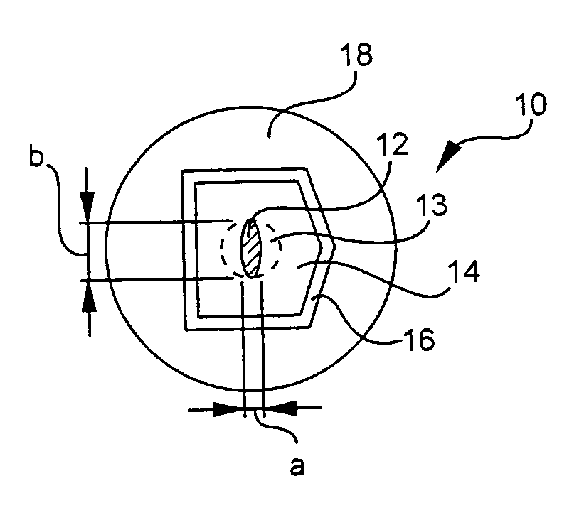
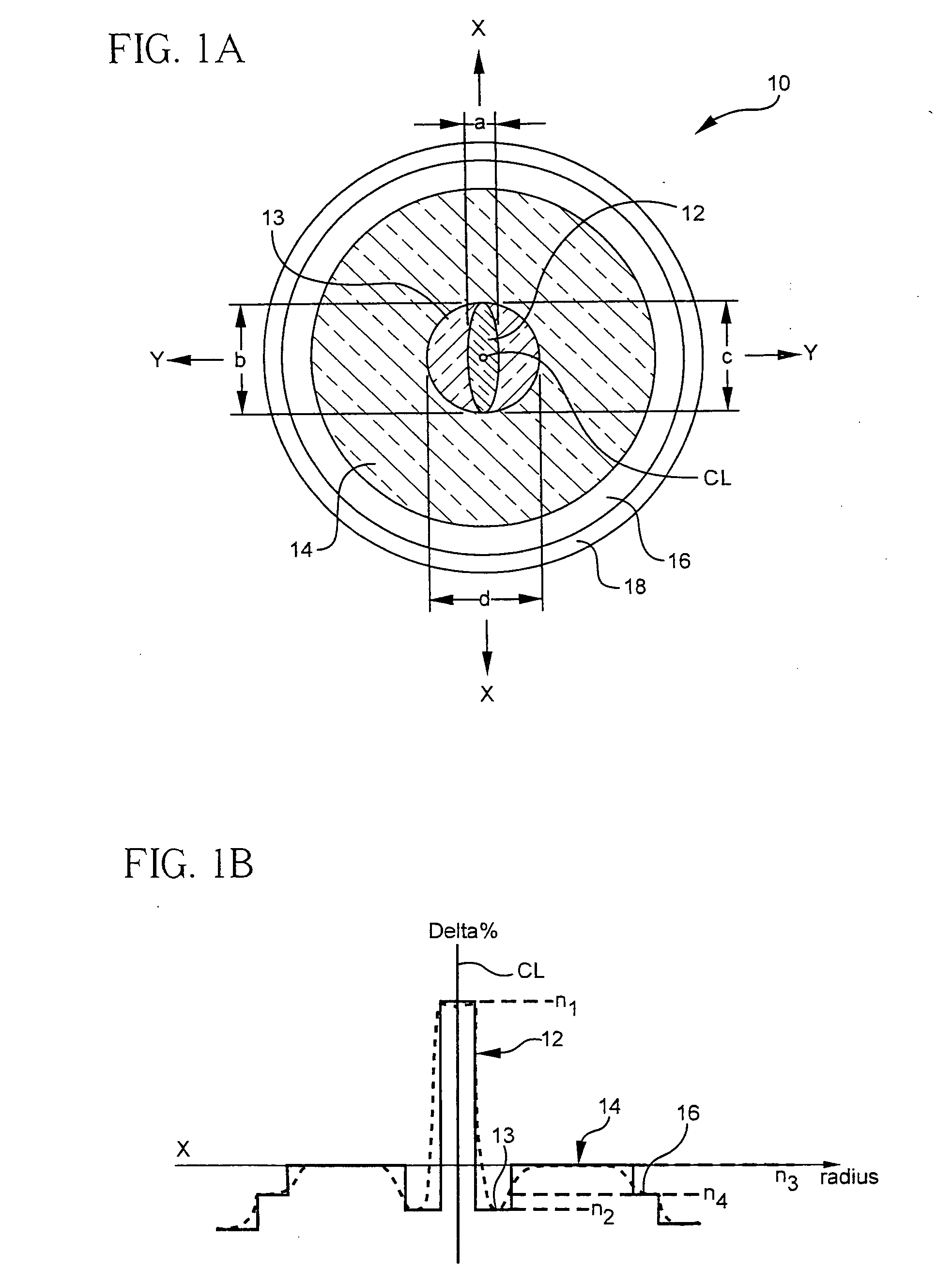
[0081]FIG. 3A illustrates a refractive index profile an exemplary optical fiber of the present invention. More specifically, FIG. 3A depicts refractive index delta as vs. the radius for this exemplary optical fiber. This optical fiber has a Yb doped, silica based core 12 which is multi mode at the lasing wavelength of 1100 μm, a B or / and F doped silica based moat 13, a silica based inner cladding 14 having two sections of almost the same index of refraction (delta % ≈0) and an outer cladding 16 which is doped with fluorine and / or B. The NA of the inner cladding is 0.16. FIG. 3A illustrates that the refractive index difference (delta %) of the core 12 is about 0.7, that the moat 13 has refractive index difference (delta %) of −0.4% and that the fluorine doped outer cladding 16 has the refractive index delta of about −0.7%.

[0082] The specific composition for the optical fiber of this example is: [0083] Core 12: 0.8 wt % Yb2O3; 9.5 wt % P2O3; 5.4 wt % GeO2; [0084] Moat 13: 1.3 wt % F;...

example 2

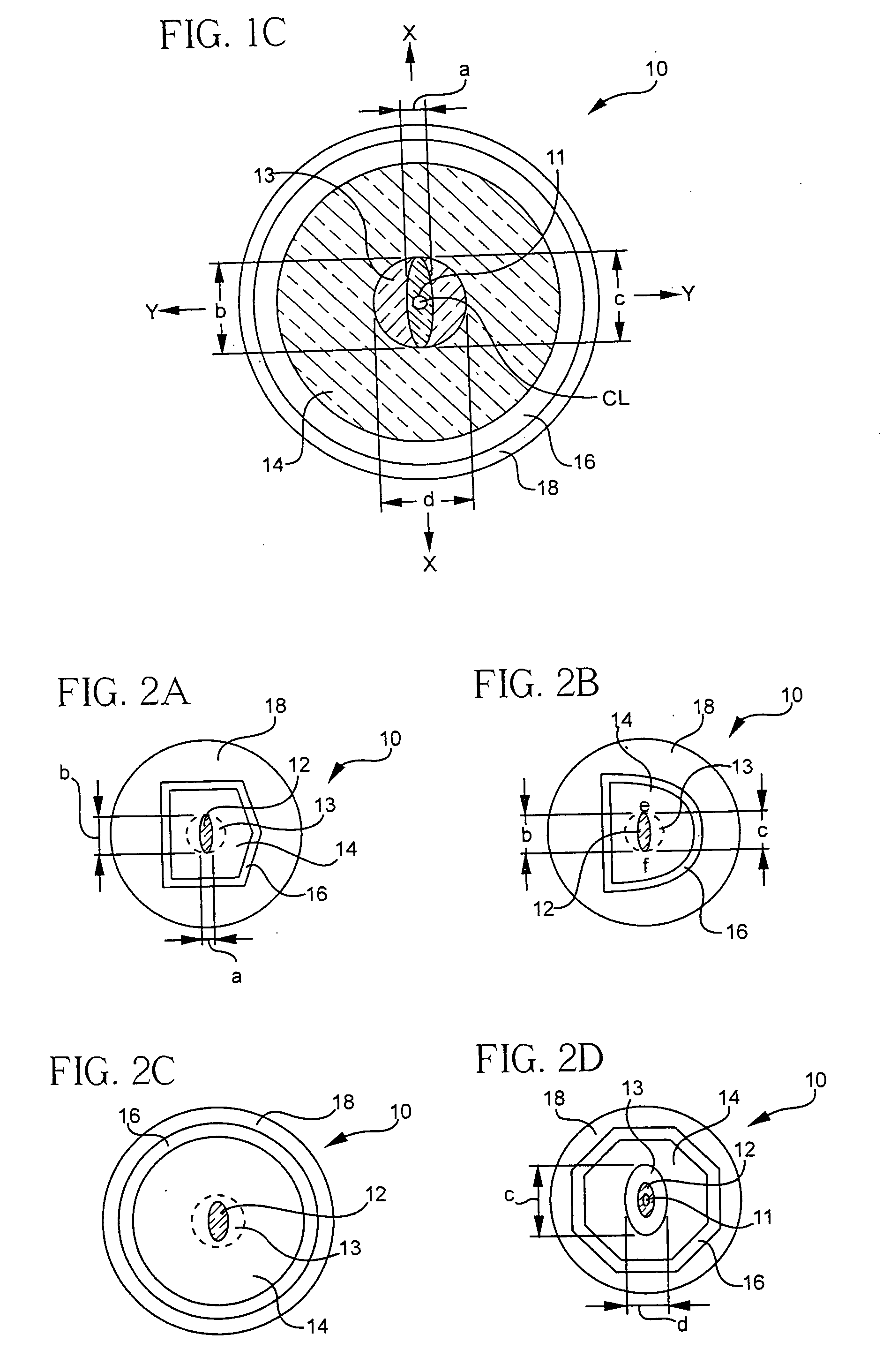
[0090]FIG. 3B illustrates schematically a refractive index profile another exemplary optical fiber of the present invention. The vertical axis of the graph of FIG. 3B depicts delta values relative to that of the inner cladding. More specifically, FIG. 3B depicts schematically refractive index delta as vs. the radius for this exemplary optical fiber. This optical fiber has a Yb doped, silica based core 12 with a center air hole 11, B or / and F doped silica based moat 13, a silica based inner cladding 14 (pure or doped silica) and an outer cladding 16 which is silica doped with fluorine and / or B. FIG. 3B illustrates that the refractive index difference (delta %) of the core 12, relative to the inner cladding 14, is about 0.3, that the moat 13 has refractive index difference (delta %) of −0.5% and that the fluorine doped outer cladding 16 has the refractive index delta of about −0.7%.

[0091] The geometrical parameters of this fiber and two other exemplary fibers are provided in Table 1,...


PUM

PropertyMeasurementUnit
wavelengthsaaaaaaaaaa

Abstract

An optical fiber, comprising: (i) a rare earth doped silica based elongated core with a first refractive index (n1) with an aspect ratio of 1:5 to 1; (ii) a silica based moat abutting and at least substantially surrounding the core, the moat having a refractive index n2, wherein n2<n1; (iii) a silica based inner cladding surrounding the moat, the inner cladding having a third refractive index (n3), wherein n1>n3; and n3>n2; (iv) a silica based outer cladding surrounding said inner cladding, the outer cladding having a fourth refractive index (n4), such that n4<n3; the optical fiber exhibits single polarization at the operating wavelength band.

Description

[0001] This Application claims the benefit and priority to U.S. Provisional Patent Application No. 60 / 621,389, filed Oct. 21, 2004. This Application also claims the benefit and priority to U.S. application Ser. No. 10 / 930,889, filed on Aug. 30, 2004.[0002] Parts of this invention were made with Government support under Agreement No. MDA972-02-3-004 awarded by DARPA. The Government may have certain rights in some of the claims of the invention.BACKGROUND OF THE INVENTION Field of the Invention [0003] The present invention relates generally to optical waveguide fibers, and more particularly to a rare earth doped optical fiber exhibiting single polarization properties. TECHNICAL BACKGROUND Background of the Invention FIELD OF THE INVENTION [0004] The present invention relates generally to double clad rare earth doped optical fibers, and particularly to all glass rare earth doped optical fibers suitable for use with high power light sources or in optical fiber lasers and optical amplifi...

Claims


Application Information

Patent Timeline
Patent Type & Authority Applications(United States)
IPC IPC(8): G02B6/02
CPCC03B37/01234C03B37/01245C03B37/01413C03B37/01446C03B2201/12C03B2201/14C03B2201/28C03B2201/31C03B2201/36C03B2203/12C03B2203/23C03B2207/90G02B6/023G02B6/024G02B6/03611G02B6/03661G02B6/03666H01S3/06716H01S3/0672H01S3/06729H01S3/1618H01S3/1695
Inventor BERKEY, GEORGE EDWARDCHEN, XINKOH, JOOHYUNLI, MING-JUNNOLAN, DANIEL ALOYSIUSWALTON, DONNELL THADDEUSWANG, JIZENTENO, LUIS ALBERTO
Owner DARPA
Why Eureka
Try Eureka