

Ceramic electronic device and production method thereof
a technology of ceramic electronic devices and ceramic plates, which is applied in the direction of fixed capacitors, natural mineral layered products, chemistry apparatuses and processes, etc., can solve the problems of large ir temperature dependence, deterioration of capacitance, and more severe environment of electronic devices, and achieve excellent temperature characteristics of capacitance, high reliability, and low ir temperature dependence
- Summary
- Abstract
- Description
- Claims
- Application Information
AI Technical Summary
Benefits of technology
Problems solved by technology
Method used
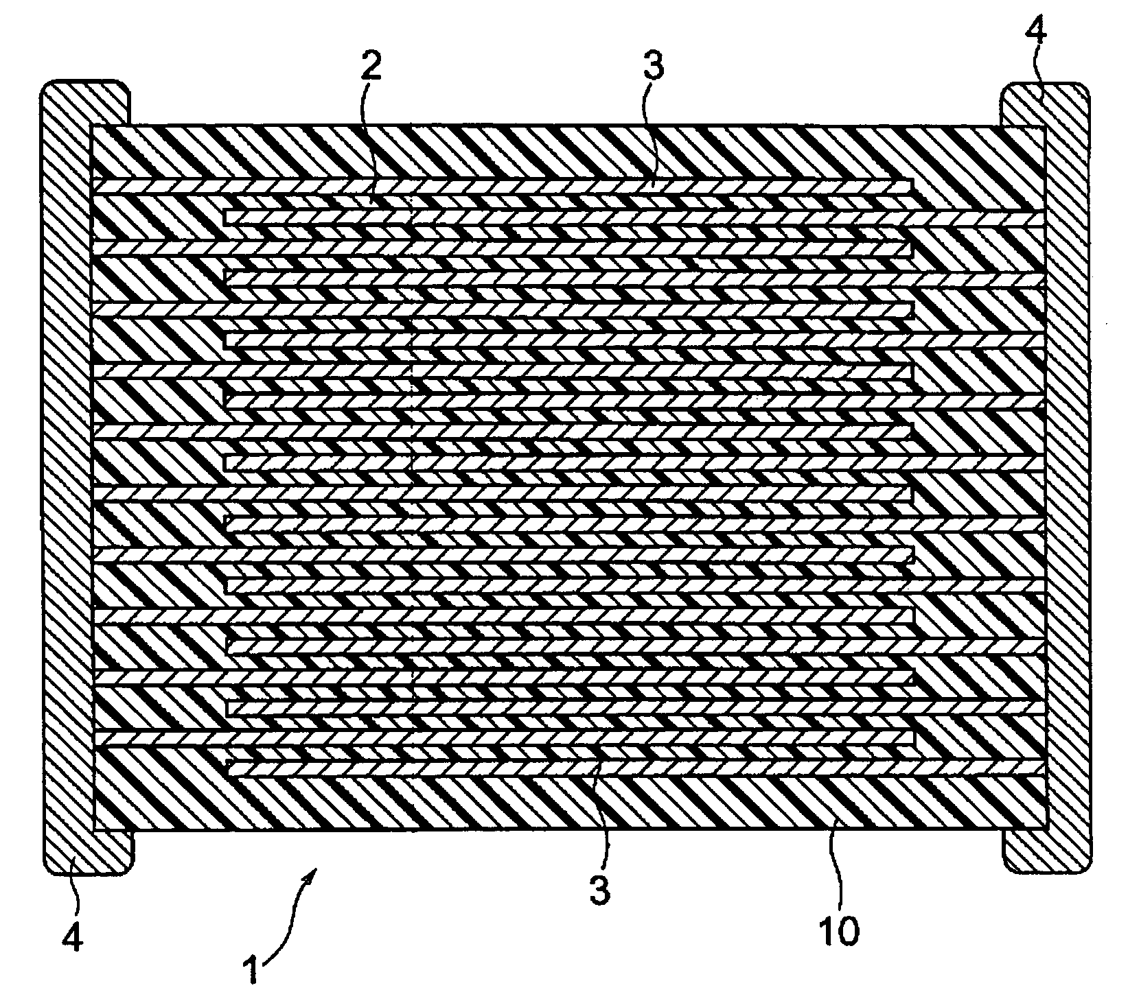
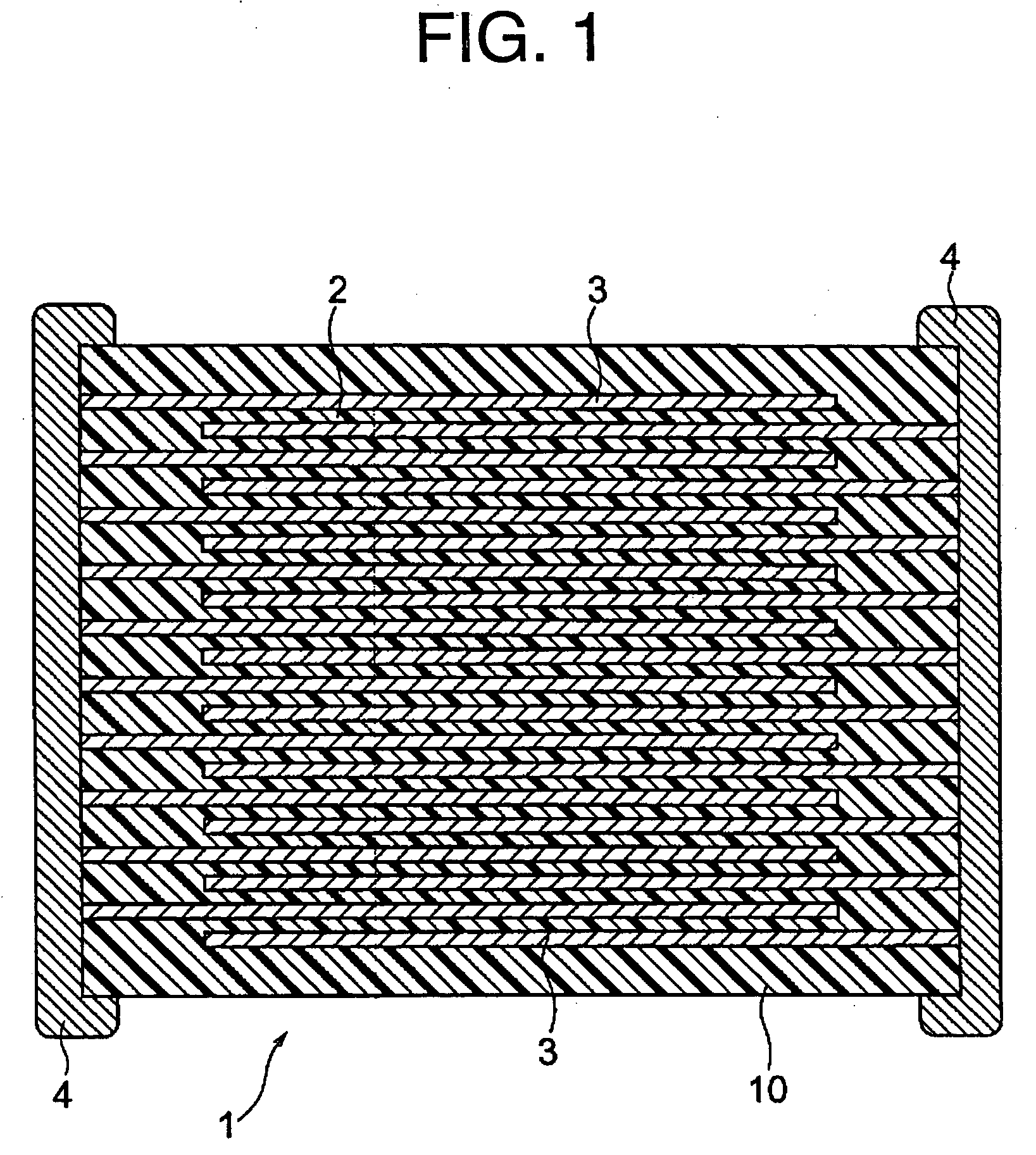
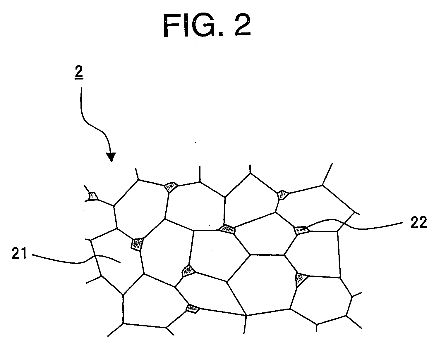
Image

Examples
example 1
[0122] First, to produce a pre-preliminarily fired powder, the main component material (BaTiO3) and subcomponent materials listed below having an average particle diameter of 0.3 μm are prepared and mixed.
[0123] MgO: 1.1 mole
[0124] V2O5: 0.06 mole
[0125] MnCO3: 0.4 mole
[0126] CaZrO3: 1.7 moles
[0127] An adding quantity of each of the subcomponents is the number of moles with respect to 100 moles of BaTiO3 as the main component.
[0128] Then, the pre-preliminarily fired powder was preliminarily fired. The preliminary firing condition was as below.
[0129] Temperature rising rate: 200° C. / hour
[0130] Holding temperature: 800° C.
[0131] Temperature holding time: 2 hours
[0132] Atmosphere: in the air
[0133] A material obtained by the preliminary firing was pulverized by a pulverizer for 1 hour to obtain a preliminarily fired powder. Then, the preliminarily fired powder was added with 1.5 moles of Al2O3 as an oxide of Al, 3.0 moles of SiO2 as an oxide of Si and 3.0 moles of Tb2O3 as an ...
examples 2 to 9
[0153] Other than respectively using the rare earth elements shown in Table 1 instead of an oxide of Tb (Tb2O3) as an oxide of R, capacitor samples of examples 2 to 9 were produced in the same way as that in the example 1, and observation of a secondary phase and evaluation of temperature dependency of the capacitance and IR temperature dependency were made in the same way as those in the example 1. The results are shown in Table 1. Note that an adding quantity of the oxide of R in each example was the same as that in the example 1.
TABLE 1Table 1TemperatureElements FormingDependency ofIR TemperatureSecondary PhaseCapacity (%)DependencyAluminumSiliconRare Earth Element125° C.150° C.125° C.150° C.Example 1AlSiTb—−5.1−13.7−0.89−1.9Example 2AlSiDy—−3.2−11.5−0.96−1.97Example 3AlSiY—−2.5−9.2−0.81−1.87Example 4AlSiHo—−2.7−9.5−0.92−1.91Example 5AlSiEr—−2.1−8.1−0.78−1.81Example 6AlSiTm—−2−7.4−0.86−1.87Example 7AlSiYb—−1.7−5.6−0.81−1.82Example 8AlSiLu—−1.5−5−0.89−1.89Example 9AlSiSc—−1.2−4....
example 10
[0157] Other than using an oxide of Dy (Dy2O3) and an oxide of Yb (Yb2O3) instead of the oxide of Tb (Tb2O3) as an oxide of R, capacitor samples of an examples 10 were produced in the same way as that in the example 1, and observation of a secondary phase and evaluation of temperature dependency of the capacitance and IR temperature dependency were made in the same way as those in the example 1. The results are shown in Table 2. Note that, in the example 10, adding quantities of Dy2O3 and Yb2O3 were 1.5 moles of Dy2O3 and 3.0 moles of Yb2O3 with respect to 100 moles of BaTiO3.
PUM
| Property | Measurement | Unit |
|---|---|---|
| temperature | aaaaa | aaaaa |
| temperature | aaaaa | aaaaa |
| thickness | aaaaa | aaaaa |
Abstract
Description
Claims
Application Information