
Microchip for sample, centrifugal dispension method of sample using the microchip and centrifugal dispenser

a microchip and dispenser technology, applied in the direction of laboratory glassware, separation processes, centrifuges, etc., can solve the problems of microchips encountering the case of samples, microchips unable to accept samples, and more difficulty in allowing samples, so as to reduce the volume of centrifugal dispensers

Inactive Publication Date: 2006-05-04
ISHIKAWA SEISAKUSHO +1
View PDF2 Cites 34 Cited by
  • Summary
  • Abstract
  • Description
  • Claims
  • Application Information

AI Technical Summary

Benefits of technology

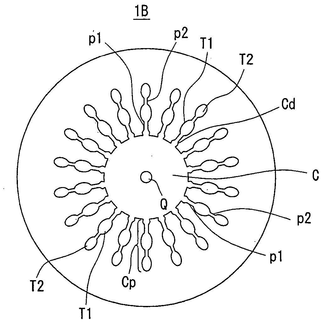
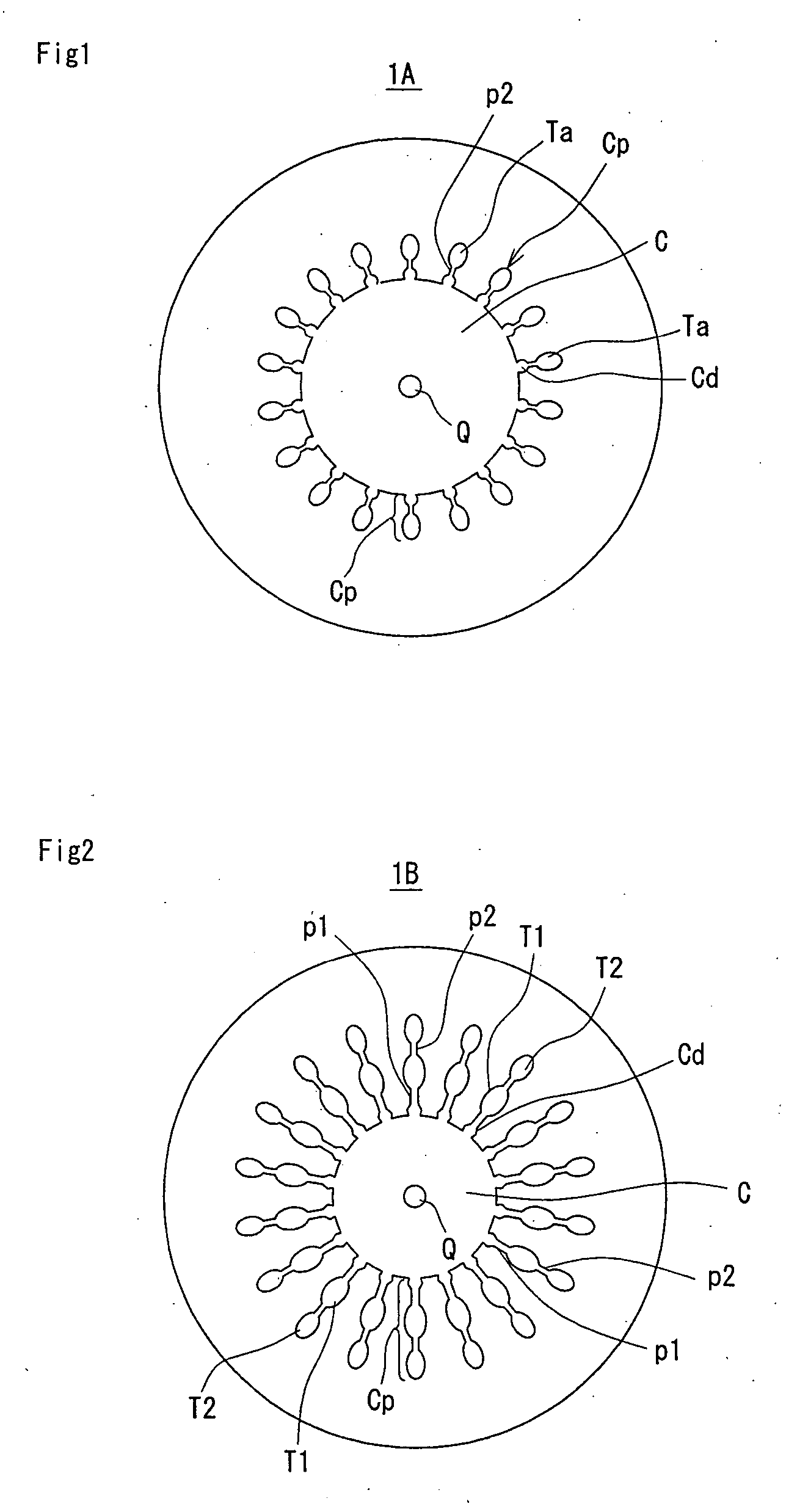
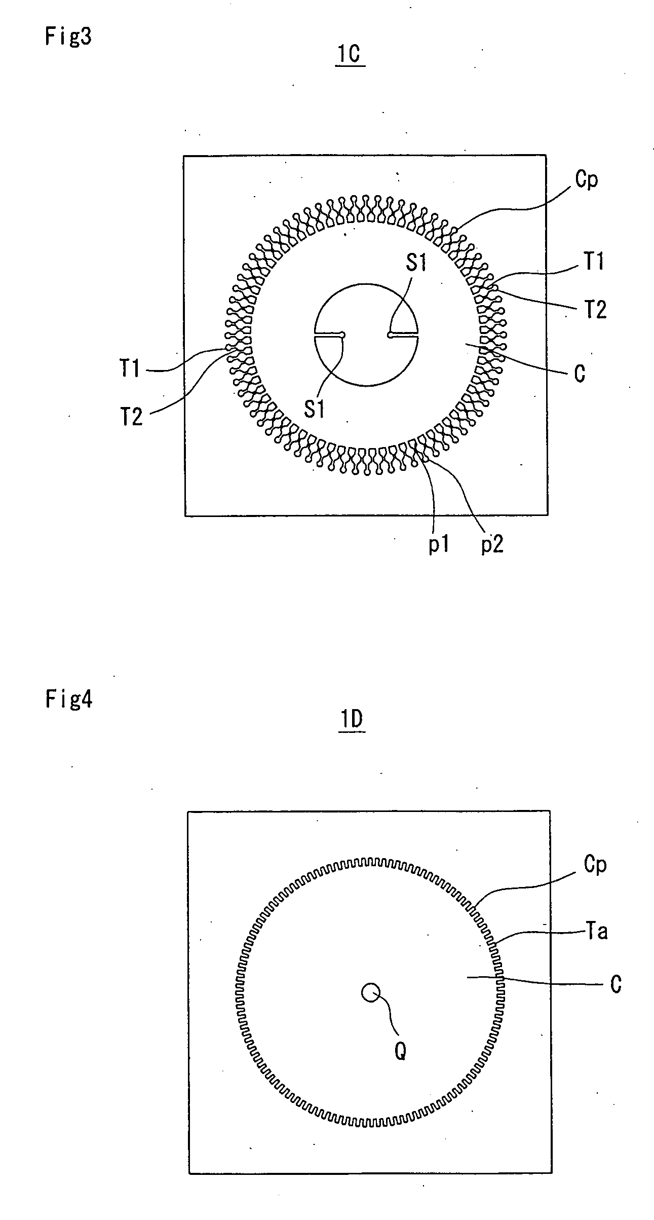
[0011] According to the second aspect of the invention, by means of the sun-and-planet rotation giving a revolving motion and a rotating motion to the rotary disk, the liquid sample dropped onto the solution-dropping portion, upon receiving both the centrifugal forces of the revolving motion and rotating motion, can uniformly be separated and poured (dispensed) into each detection chamber for a short period of time in the form of flowing into it.
[0017] According to the fifth aspect of the invention, the revolving motion about the central gear and rotating motion about the shaft of the rotary disk are given to the rotary disk by the drive means. In addition, by disposing the central gear at the center of the arm as suspended from the center and in alignment with the shaft of the drive means, it is made possible to stabilize the sun-and-planet rotation and reduce the centrifugal dispenser in volume.
[0018] The microchip of the present invention for a liquid sample is only required to pour the liquid sample onto the solution-dropping portion at the center thereof. By giving a revolving motion and a rotating motion to the rotary disk on which the microchip is mounted using the centrifugal dispensing method of the sample and the centrifugal dispenser according to the present invention, the sample can uniformly be dispensed into each detection chamber for a short period of time without inducing the variation in the amount of the sample in the detection chambers and the back-flow of the sample. Furthermore, this uniform dispensing can be attained even in the case where plurality of radial channel patterns are slightly deviated from the center of the rotary disk, where the microchip is not accurately disposed at the mounting position of the centrifugal dispenser or where the shaft of the motor that is the drive means is deviated. In spite of the relatively simple structure of the centrifugal dispenser comprising the arm rotated by the drive means, the rotary disk provided with the peripheral gear and the central gear engaging with the peripheral gear, use of the conventional expensive spotter device large in size is not required and the drive means can give a revolving motion and a rotating motion to the rotary disk. This is very advantageous.

Problems solved by technology

When the position is slightly displaced, the sample would fail to flow into a prescribed position (into the waste chamber, for example) and flow deviation and possible back-flow will arise, which are problematic.
Particularly, an increase in the number of channel patterns makes the width of the flow path narrower, resulting in encountering more difficulty in allowing the sample to run into a prescribed position (into the waste chamber, for example).
Furthermore, this microchip has encountered the case where the sample even when rotated by the rotating device cannot be poured into a prescribed position (into the waste chamber, for example).
In order to make an assay using a conventional microchip for a sample, use of a large-sized expensive spotter device (the aforementioned multiple pipetter mechanism) and a mechanism for precisely moving the device in the X- and Y-directions is required, resulting in the place and equipment on a grand scale and high cost.

Method used


Image

  • Microchip for sample, centrifugal dispension method of sample using the microchip and centrifugal dispenser
  • Microchip for sample, centrifugal dispension method of sample using the microchip and centrifugal dispenser
  • Microchip for sample, centrifugal dispension method of sample using the microchip and centrifugal dispenser

Examples


example 1

[0048] The PCR is the abbreviation of a polymerase chain reaction that is the technology for replicating, based on a specific gene arrangement, the gene million-fold for a short period of time. It has recently been subjected to utilization when diagnosing and detecting a genetically determined disease, virus or bacillus from blood, marrow liquid, cerebrospinalis liquid, etc. besides the utilization in the bioengineering field. By analyzing the process of this production, it is possible to determine the quantity of the DNA content itself. The PCR comprises the following six procedures, i.e. of (1) extracting a DNA, (2) heating a DNA double helix to form a single-strand DNA, (3) allowing the gene comprising four bases to be bonded with a specific base, (4) preparing a target gene based on this base sequence that is the gene arrangement and adding thereto a gene fragment (primer) paired with the target gene, (5) allowing the primer to be bonded with the gene arrangement aimed at and (6...

example 2

[0053] A microchip 1E shown in FIG. 13 was used, in which 25 μl of a blue dye (bromophenol blue) solution was dropped into the central input port Q thereof and given a sun-and-planet rotation, and the revolution per minute (rpm) when all the chambers T1 had been filled with the solution was examined. The microchip 1E fabricated as shown in FIG. 13 had PDMS attached to a silicon wafer cut to 40 mm square by means of oxygen plasma. Four kinds of microchips 1E were fabricated in which the flow paths p2 had a length M5 of 2 mm, a width M6 varied to 1000 μm, 750 μm, 500 μm and 250 μm and a depth of 120 μm. In the four microchips 1E, a length M1 is 30.5 mm and M2 19.3 mm, and the detection chamber T1 has a length M3 of 3 mm and a width M4 of 2 mm.

[0054] The experimental results using the centrifugal dispenser 11 were 950 rpm in the case of the microchip having the flow path p2 of the width M6 of 1000 μm, 1050 rpm in the case of the microchip having the flow path p2 of the width M6 of 750...


PUM

PropertyMeasurementUnit
diameteraaaaaaaaaa
diameteraaaaaaaaaa
depthaaaaaaaaaa

Abstract

A microchip used for a method for centrifugally dispensing a liquid sample by giving a revolving motion and a rotating motion to a rotary disk on which the microchip is mounted, includes a solution-pouring portion at a center thereof onto which the liquid sample is poured and channel patterns extending outward, with the solution-pouring portion as a center, and forming therein flow paths for the liquid sample and detection chambers which constitute portions for examining the liquid sample and in which the liquid sample is centrifugally dispensed. A centrifugal dispensing method using the microchip includes giving a revolving motion and a rotating motion to the rotary disk on which the microchip is mounted, thereby centrifugally dispensing the liquid sample in the detection chambers. A centrifugal dispenser using the microchip includes a rotary disk on which the microchip is mounted, means for revolving the rotary disk about a shaft and means for rotating the rotary disk about another shaft of the rotary disk.

Description

BACKGROUND OF THE INVENTION [0001] 1. Field of the Invention [0002] The present invention relates to a microchip for a sample that performs chemical reaction, biochemical reaction, blood examination, etc. with high efficiency using a minute amount of reaction liquid or a sample, to a centrifugal dispensing method of a sample using the microchip and to a centrifugal dispenser. [0003] 2. Description of the Prior Art [0004] A microchip for a sample used when detecting and diagnosing a target gene (DNA), for example, from an infinitesimal sample has therein a flow path (channel pattern) of a microscopic cross section having a specific shape suited for checkup purposes and is used when making a prescribed medical evaluation by feeding a sample liquid under test from a flow-type input port into a channel pattern and making a gene amplification reaction, for example, or when making a prescribed evaluation by filling a channel pattern with a sample and reacting the sample by the application...

Claims


Application Information

Patent Timeline
Patent Type & Authority Applications(United States)
IPC IPC(8): C02F1/38B01L3/00B01L7/00G01N33/52G01N33/543G01N35/00G01N35/08G01N37/00
CPCB01L3/50273B01L7/52B01L2300/0803B01L2300/0864Y10T436/25375B01L2400/0409G01N35/00029G01N2035/00158B01L2300/087
Inventor KOBAYASHI, MASAAKIICHIKAWA, HIROSHITAMIYA, EIICHI
Owner ISHIKAWA SEISAKUSHO
Learn More