Low esr switch for nuclear resonance measurements

a low-esr switch and nuclear resonance technology, applied in magnetic measurements, geological measurements, reradiation, etc., can solve the problems of high esr and easy ‘catching', and achieve the effect of increasing the sensitivity of the system, reducing the resistance of the coil-capacitor circuit, and increasing the q of the system

Inactive Publication Date: 2006-05-04
QRSCI
View PDF19 Cites 1 Cited by
  • Summary
  • Abstract
  • Description
  • Claims
  • Application Information

AI Technical Summary

Benefits of technology

[0009] It is an object of the present invention to lower the resistance of a coil-capacitor circuit in a nuclear or electron resonance system, such as involving NQR, NMR, electron spin resonance or MRI to increase the Q of the system and thus increase the sensitivity of the system.
[0010] The present invention seeks to solve the problem of lowering the resistance of a coil-capacitor circuit by introducing a low equivalent series resistance (ESR) switch. The introduction of this switch lowers the resistance of the coil-capacitor circuit and results in a higher Q than would otherwise be achieved if relays or semiconductor devices were used.

Problems solved by technology

The switch ideally needs to have zero ESR, however this is unrealistic.
An inherent problem with mechanical relays is that they have a high ESR and are prone to ‘catching’ after many operations.

Method used


Image

  • Low esr switch for nuclear resonance measurements
  • Low esr switch for nuclear resonance measurements
  • Low esr switch for nuclear resonance measurements

Examples


first embodiment

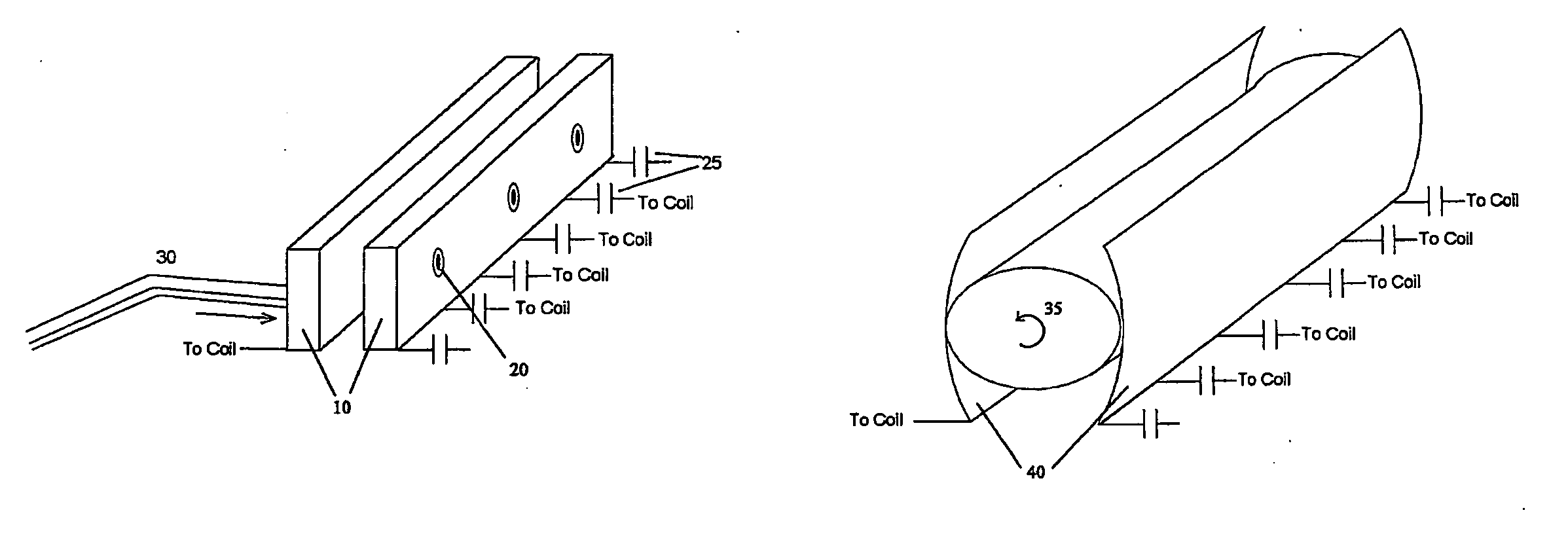
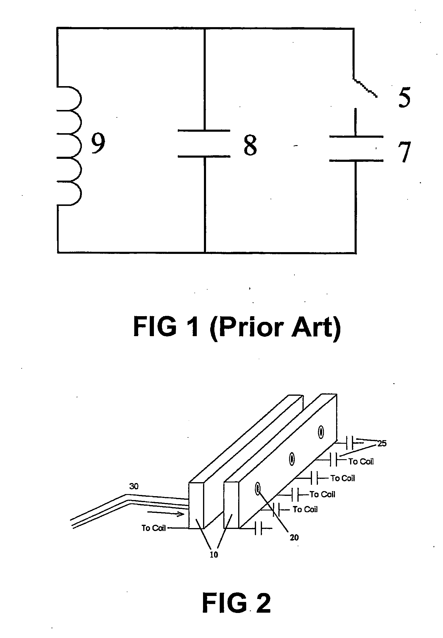
[0033] the best mode is directed towards an ESR switch of the form shown in FIG. 2. The switch comprises two flat parallel metallic bars 10 having a mutually large contact surface area, which in their quiescent position, are separated by a small distance. An actuating means in the form of a pneumatic air piston system or a motor or solenoid (not shown in FIG. 2) drives the two bars together when contact is required. Alignment is maintained through insulated guide rods 20. In practice, this action normally occurs under the direction of a controlling computer.

[0034] The large contact surface area of the switch provides extra surface area for the current to flow over thus minimising the resistance. This switch allows the operator to increase the capacitance of the circuit without detrimentally compromising the resistance and thus the Q of the coil-capacitor system.

[0035] For example in NQR, when switching from RDX to PETN frequencies, a large insertion of capacitance into the circuit ...

third embodiment

[0042] The third embodiment is the same as the first, except that the entire switch is isolated inside a vacuum. The use of a vacuum chamber around the metal bars prevents the oxidation of these bars allowing an increase in the useable lifetime of the switch.

fourth embodiment

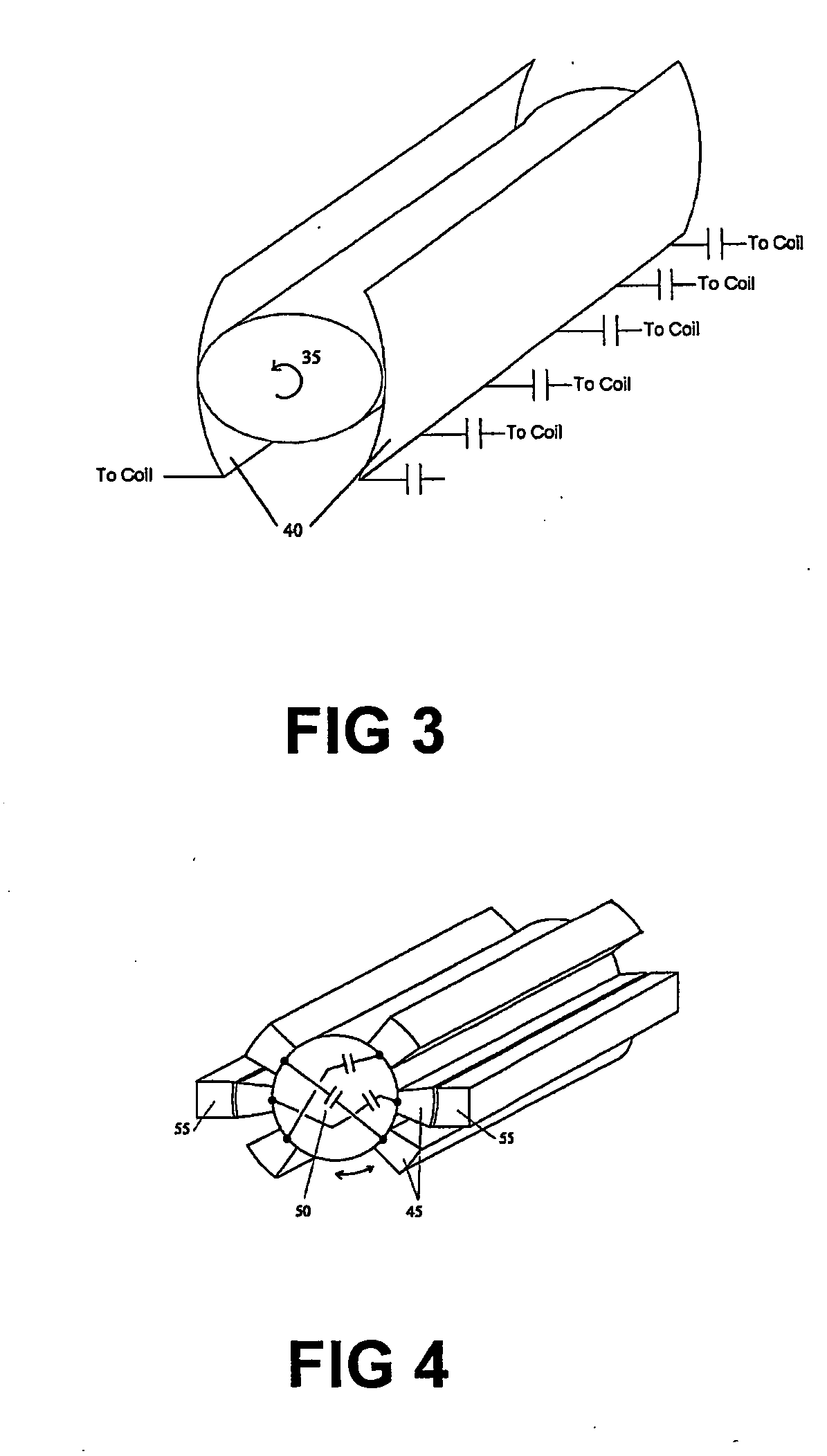
[0043] The fourth embodiment is similar to the preceding embodiments, except that it involves adding a low ESR switch of the type shown in FIG. 3 to the coil-capacitor circuit of an NQR, NMR, electron spin resonance or MRI system.

[0044] As shown, the low ESR switch consists of a rotatable oval cross-section shaped metallic bar 35 lying between two concave plates or bars 40, having a mutually large contact surface area. An actuating means in the form of a pneumatic air piston system or a motor or solenoid turns the oval cross-section shaped bar to contact the plates 40 when contact is required. This action occurs under direction from a controlling computer. The large contact surface area of the switch provides extra surface area for the current to flow over thus minimising the resistance. This switch allows an increase in the capacitance of the circuit without detrimentally compromising the resistance and thus the Q of the coil-capacitor system.

[0045] The fifth embodiment is the sam...


PUM


Abstract

A low equivalent series resistance (ESR) switch for selectively adding to a coil-capacitor circuit of a nuclear or electron resonance system. The switch comprises a pair of physically and electrically contacting members having mutually large contact surface areas. The members are movable between a quiescent position where the contact surface areas are separated by a small distance and an active position where the contact surface areas are brought into physical and electrical contact to connect into the coil-capacitor circuit.

Description

FIELD OF THE INVENTION [0001] This invention relates to the detection of particular substances using nuclear and electronic resonance detection technology. It has particular application, with respect to nuclear quadrupole resonance (NQR), but some aspects of it also have application with respect to nuclear magnetic resonance (NMR), magnetic resonance imaging (MRI) and electron spin resonance technologies. [0002] More specifically the invention relates to switching between substantially different frequencies, whilst maintaining a low Equivalent Series Resistance (ESR) resistance across a resonant coil for the purposes of nuclear resonance detection. [0003] Throughout the specification, unless the context requires otherwise, the word “comprise” or variations such as “comprises” or “comprising”, will be understood to imply the inclusion of a stated integer or group of integers but not the exclusion of any other integer or group of integers. BACKGROUND ART [0004] The following discussio...

Claims


Application Information

Patent Timeline
Patent Type & Authority Applications(United States)
IPC IPC(8): G01V3/00G01R33/34G01R33/36G01R33/44G01R33/60
CPCG01N24/084G01R33/3628G01R33/3635G01R33/3664G01R33/441G01R33/60
Inventor FLEXMAN, JOHN HAROLDAITKEN, CHRISTOPHER NORMAN
Owner QRSCI
Why Eureka
Try Eureka